In this project, we will make a CD4047 Inverter Circuit, and we will also discuss why this type of inverter is not a good or reliable solution for real-world applications.
An inverter is an electronic device that converts DC voltage into AC voltage. Inverters play a very important role in power backup systems, especially in remote locations such as villages, where frequent power cuts are common. In many places, even in cities, power cut-off problems still exist, and in such situations, an inverter becomes a necessity.
Commercially available inverters are quite expensive, which motivates electronics hobbyists and beginners to try DIY inverter circuits. So, in this article, we will start with our DIY CD4047 inverter project, mainly for learning and experimental purposes.
Introduction to the DIY CD4047 Inverter
Let us make a simple homemade inverter. This inverter is not meant for professional or commercial use. It is just a fun and educational project that can power a 50W to 100W light bulb or a small table fan. However, the fan may create noise due to the impure and non-sinusoidal AC input provided by this inverter.
This circuit cannot compete with any inverter available in the market, because commercial inverters provide regulated voltage, feedback control, and pure sine wave output, which this circuit lacks.
This project helps beginners understand:
- Basic inverter operation
- Square wave generation
- MOSFET switching
- Transformer-based voltage conversion
Purpose of Inverter
An inverter converts DC power (from a battery) into AC power, which is required to operate most household appliances. Since batteries store energy only in DC form, an inverter is required whenever AC power is needed during power outages. Inverters are commonly used in homes, offices, rural areas and emergency power systems.
Related Articles:
- SPWM Inverter Block Diagram and Working
- H Bridge Inverter Circuit using IC SG3525 and MOSFET IRFZ44N
- SG3525 PWM Inverter Circuit Diagram and it’s Working
- 12V to 230V Inverter Circuit Diagram using 555 timer IC
Why IC CD4047 Is Used in This Inverter Circuit
Now the question arises: Why is IC CD4047 used here?
The answer is simple, in an inverter, we need to drive the gates of MOSFETs. To do this, we require a circuit that can generate alternating pulses. The CD4047 IC performs this task by generating a square wave output.
- The IC produces two output signals
- These signals are 180 degrees out of phase
- They are used to alternately switch MOSFETs ON and OFF
Most low-cost power inverters use this same technique to drive MOSFETs or power transistors.
About IC CD4047
The CD4047 is a monostable/astable multivibrator IC. It is widely used in timing and oscillation-based circuits.
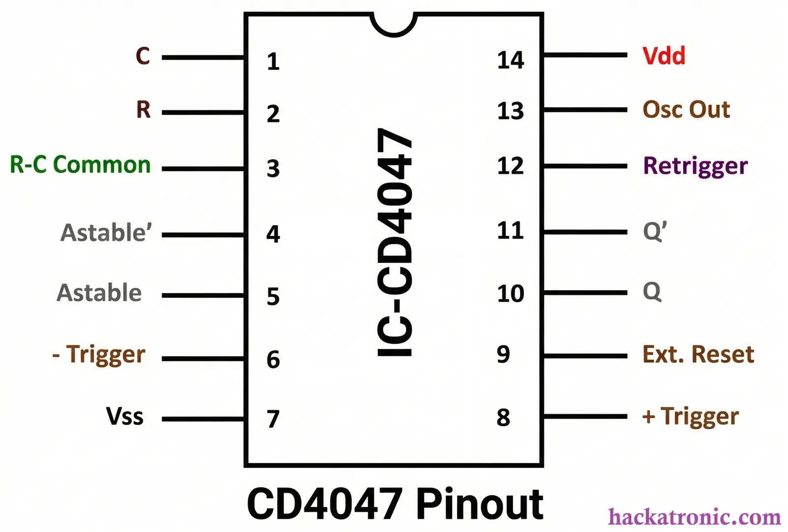
Features of IC CD4047
- 14-pin IC
- CMOS logic based
- Can operate in:
- Monostable mode
- Astable mode
- Requires very few external components
- Low power consumption
- Operating voltage range: 3V to 15V
- Works best at 5V DC supply
- Provides complementary outputs
Because of these features, CD4047 is very easy to use and is commonly found in beginner-level electronics projects.
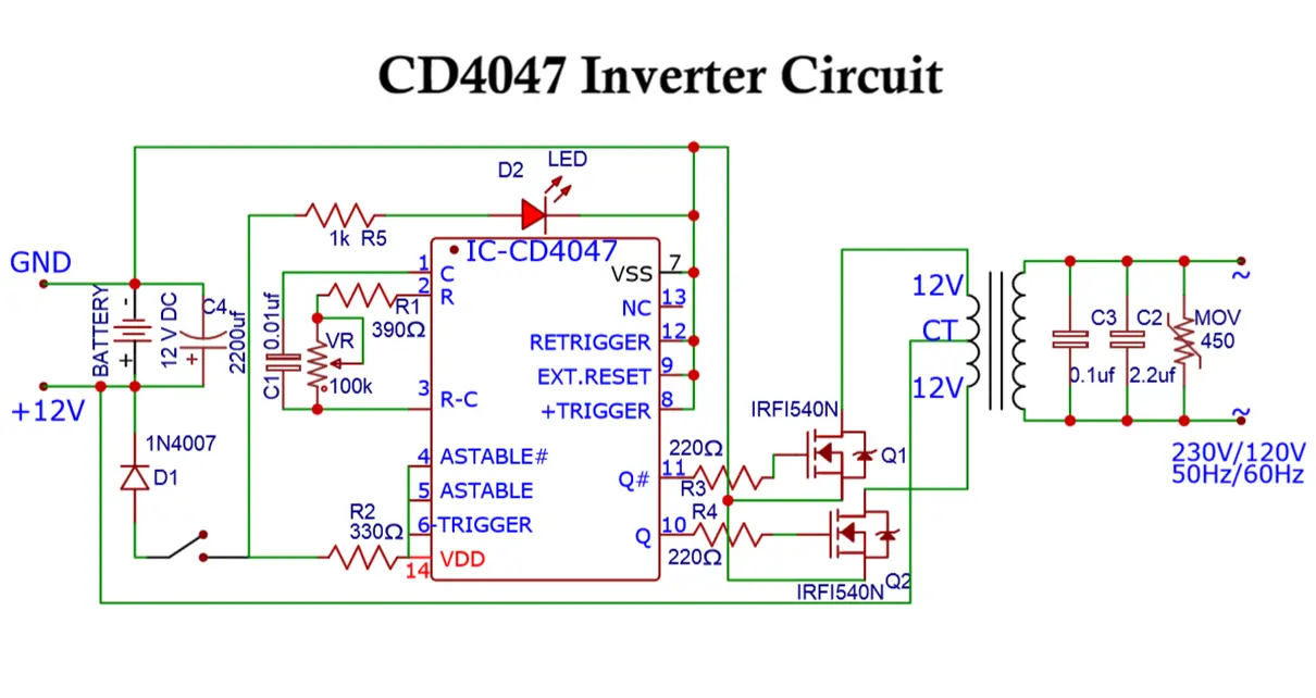
CD4047 Inverter Circuit Diagram
The circuit diagram of the CD4047 inverter is very simple and easy to understand.
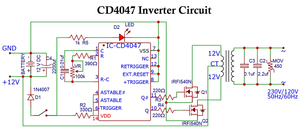
The main parts of the circuit include:
- IC CD4047
- Two MOSFETs (IRF540)
- Center-tapped transformer
- Battery
- Frequency-setting components
The IC CD4047 drives the two MOSFETs, which are connected in a push-pull configuration.
Working Principle of the Circuit
A normal transformer cannot work with DC, because DC does not produce a changing magnetic field. Therefore, to make the transformer work, the circuit must produce time-varying current.
This is achieved by switching the MOSFETs ON and OFF alternately.
As a result:
- Magnetic flux is induced in the transformer core
- This flux induces voltage in the secondary winding
- AC voltage appears at the output
Frequency Control: The frequency of the output AC depends on resistor, capacitor and potentiometer. A potentiometer is used to adjust the frequency to the desired value. Usually, 50 Hz is used in most countries, and 60 Hz is used in some regions
Transformer and Battery Selection:
- The transformer must be:
- Center tapped
- Rated for sufficient power
- Capable of handling the expected load
- If the transformer rating is low, it may:
- Overheat
- Produce voltage drop
- Get permanently damaged
- The battery should be:
- 12V DC
- Greater than 10Ah capacity
- A low-capacity battery will:
- Drop voltage quickly
- Reduce output voltage
- Shorten backup time
LED Indicator: An LED is used in the circuit to indicate that the inverter is ON.
⚠️ Warning: When the inverter is ON, do not touch the circuit. The output voltage is 230V AC, which can cause serious harm.
Components List
- IC – CD4047
- Transformer – Center-tapped (12V to 230V)
- R1 – 390Ω (¼W)
- R2 – 330Ω (¼W)
- R3, R4 – 220Ω (¼W)
- R5 – 1kΩ (¼W)
- VR – 100kΩ variable resistor
- C1 – 0.01µF
- C2 – 2.2µF (450V)
- C3 – 0.1µF (450V)
- C4 – 2200µF (25V)
- D1 – 1N4007
- D2 – LED (any color)
- Q1, Q2 – IRF540 MOSFETs (100V, 33A, 140W)
Detailed Working of CD4047 Inverter
In the above circuit, the battery provides 12V DC along with sufficient current. The IC CD4047 operates in astable mode, which means it continuously switches its output states.
- Output at pin 10 and pin 11 changes continuously
- These outputs are complementary (opposite to each other)
- A square wave signal is produced
These two output pins are connected to the gate terminals of the MOSFETs, which are arranged in push-pull configuration.
At any given time:
- Only one MOSFET is ON
- The other MOSFET remains OFF
The MOSFETs are capable of handling very high current.
Current Flow Explanation
- The source terminals of both MOSFETs are connected to ground.
- The drain terminals are connected to the two ends of the transformer winding.
- The center-tapped wire of the transformer is connected to +12V DC.
When MOSFET Q1 Is ON
The current path is: +12V → Transformer winding → MOSFET Q1 → Ground
When MOSFET Q2 Is ON
The current path is: +12V → Transformer winding → MOSFET Q2 → Ground
This alternate switching produces an alternating current in the transformer winding.
AC Voltage Generation
Due to alternating current in the transformer winding:
- A changing magnetic flux is produced
- This flux induces voltage in the secondary winding
- The output voltage is high-voltage AC, but it is not sinusoidal.
- Instead, the waveform is a square wave AC.
Load Capability
This square wave AC output can easily run:
- 100W incandescent bulb
- Small table fan
- Some less sensitive electronic devices
However, it is not suitable for sensitive loads such as computers, audio equipment and medical devices.
Important Precautions
- Use good quality and large heat sinks with MOSFETs
- MOSFETs get hot during operation
- Heat sinks prevent overheating and damage
- Be extremely careful while working with 230V AC
- Always disconnect power before making changes
Battery Charging Consideration
To charge the battery, you can refer to an automatic 12V battery charger circuit.
- Relays are required to switch between inverter and charging mode
- If AC mains is present, the battery should charge
- If AC mains fails, the inverter should turn ON
Why This CD4047 Inverter Is Not Good or Reliable
Although this circuit works, it is not a reliable solution for practical use due to the following reasons:
- The output waveform is not sinusoidal
- Cannot be used for sensitive electronic loads
- Output voltage directly depends on input battery voltage
- Small voltage change at input causes large output fluctuation
- Battery voltage may fluctuate or become imbalanced under load
- No feedback loop to regulate output voltage
- Frequency changes with load
- Poor voltage regulation
- No overload or short-circuit protection
See the datasheet of CD4047 IC for more detailed information.
Conclusion
The CD4047 inverter circuit is good for learning and experimentation. It helps beginners understand:
- Basic inverter design
- MOSFET switching
- Transformer operation
- Square wave AC generation
However, it should not be considered a replacement for commercial inverters. if you have any query related to this circuit, feel free to ask.
H Bridge Inverter Circuit using IC SG3525 and MOSFET IRFZ44N
