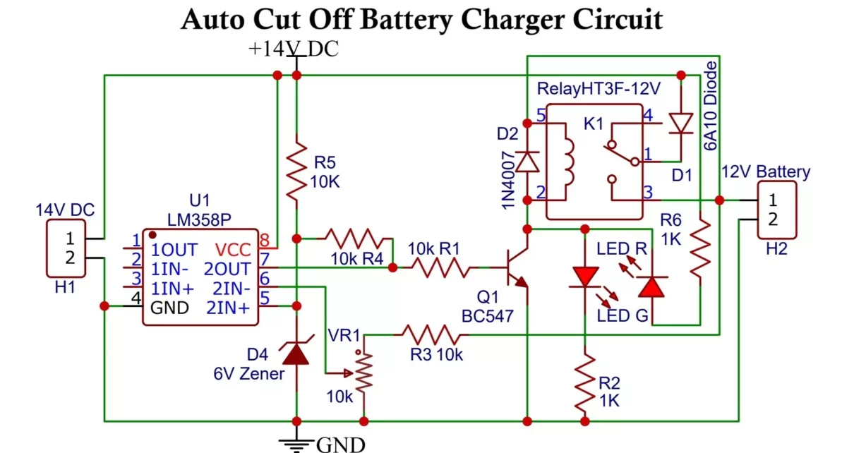
Automatic battery charger circuit:
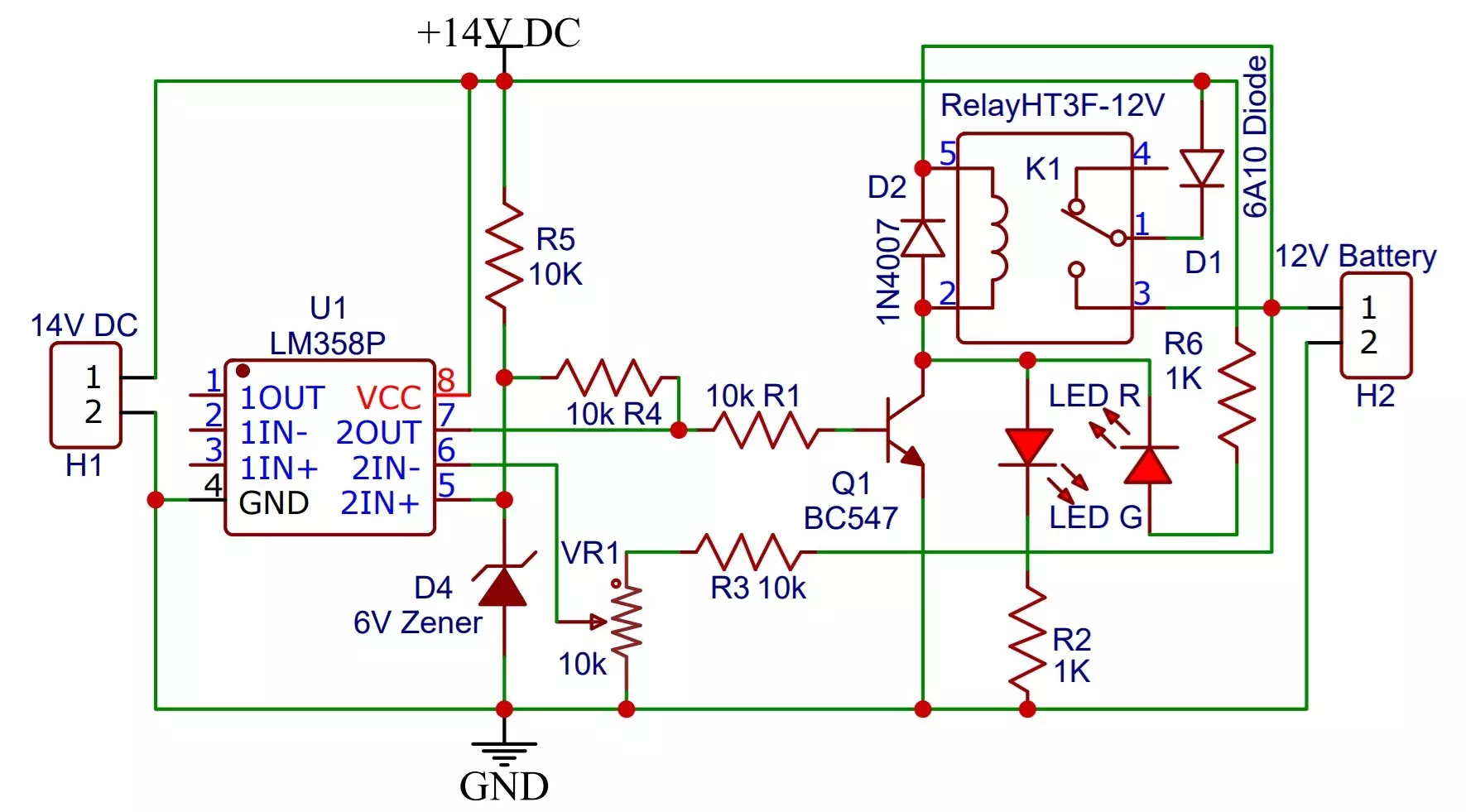
Battery Charger Components:
- R1, R3, R4, R5 10k, R2, R6 1K (1/4watt)
- VR1 10k potentiometer
- HT3F-12V Relay
- D1 6A10 Diode
- D2 1N4007
- D4 1N5233B (6V Zener)
- Q1 BC547
- U1 LM358
- LED G (green)
- LED R (red)
- 12V battery
- 2 pin PCB screw terminal 2
Working of automatic battery charger circuit:
First of all, the 220V AC is stepped down by transformer to 15V. Then it is rectified and smoothen by capacitor C1. It is regulated to 14V by using voltage regulator Lm317. Then it is fed to the battery charging circuit. To set the threshold voltage also called as cut off voltage for Battery charging, LM358 and potentiometer VR1 (or trimmer) have been used.
We apply a reference voltage on the non-inverting pin of LM358. The threshold voltage is applied at the inverting pin of the opamp. If Battery charges up to threshold voltage, opamp will turn OFF the transistor which acts as a switch and relay will be de-energized. This turns off battery charging process. the upper threshold voltage of Lead acid battery is 12.8V and lower threshold voltage is 11.5V.
This happens as the battery charges to the set threshold potential, the voltage at inverting pin of OPAMP becomes higher than non-inverting pin. The output of OPAMP becomes low which turns OFF transistor making relay OFF. This cuts power supply to the battery. If there is a high input voltage the Zener diode breaks to protect circuit.
LED Indication:
During the charging process, Red LED glows which indicates that the battery is charging. When the battery gets fully charged its voltage reaches the threshold voltage, this voltage changes the output of the OP-AMP to low. This changes the position of the relay to switch off the circuit Green LED will glow pointing to the completion of charging. Both the LEDs are connected in such a way that only one LED will glow at a time due to posit or negative voltage present at collector terminal of BC547 transistor. If you have more powerful relay, use more powerful transistor.
How to set the battery cutoff threshold:
Initially keep the power to the circuit switched OFF.
Connect a variable DC power supply source across the battery points of the circuit.
Apply a Voltage that equals to the cutoff threshold voltage of the battery. Then adjust RV1 so that relay just activates, that is the cut-off voltage.
For a 12V battery, it is nearly 13V and for a Li-Po battery, it is 4.35V.
To charge Li-Po battery you can use this 5V charger circuit.
The setting up of the circuit is done.
Remove the external variable voltage source and replace it with a battery for charging purposes.
Variable Power Supply Circuit:
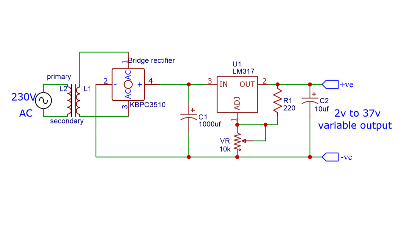
The above circuit is a variable power supply circuit. This circuit can give an output voltage ranging from 1 or 2 to 37 volts and an output current up to 1.5A. you can use the above circuit to make a variable power supply.
Working of the circuit:
The transformer used in the above circuit is having a 15V, 3A output. Then we have used the KBPC3510 rectifier to rectify the AC output of transformer. The rectifier converts Sinusoidal AC into a unidirectional DC pulsating Voltage having AC component and fluctuations.
A 1000uf polar capacitor is used to smooth out the DC supply. After this, by using IC LM317 the DC output is controlled. By using the 10k potentiometer the output DC voltage can be controlled. Further, the 10uf cap is used for a varying load.
Components:
- T1 15V Transformer (3A)
- KBPC3510 Bridge diode
- C1 1000uF (25V electrolytic)
- C2 10uF (non-polar)
- R1 220Ω
- VR 10kΩ
- LM317 IC

Hi
Can you explain the function of RV2?
Also is the value of the Zener diode critical?
I am trying to charge an old 9Volt battery from a Solar panel.
I have seen many circuit ideas 555 timer 741 op amp all with Zener diodes but nobody addresses the value of the Zener. ie should it be changed depending on battery voltage.
Thanks
Mike
yes it should be according to the battery specifications
Hello, I would like to make use of the above circuit to cutoff my inverter charging, my concern really is that the cutoff is to the AC supply, which chatters when the threshold is reached, making the cutoff unstable. Can this this circuit be applied to get rid of that flickering. Help me please…
This is a simple circuit to cut-off battery charging, for inverter you need some extra circuit for switching the load from battery to mains.
Are you trying to make inverter, or you have one?
How should I convert this charger to charge for 24 V .
Yes
Setting of VR1 is cut off voltage but, can you please explain the setting of VR2 ?
Thank You,
Ken
Circuit have been updated
Please, what value of zener diode should I need to charge 12v batteries? I made this circuit with a 6v diode and it doesn’t work, I tried with 12v and it still doesn’t work… I would be grateful for an explanation. Thanks.
Set the potentiometer properly check voltage, check opamp stage individually, check wheather relay is working properly or not
Please, what value of zener diode should I need to charge 12v batteries? I made this circuit with a 6v diode and it doesn’t work, I tried with 12v and it still doesn’t work… I would be grateful for an explanation. Thanks….
It should work
Please, what value of zener diode should I need to charge 12v batteries? I made this circuit with a 6v diode and it doesn’t work, I tried with 12v and it still doesn’t work… I would be grateful for an explanation. Thanks..🙂
Check the circuit it should work I have updated it.
You can use a multimeter to check if there is any fault.
everything is connected correctly, I installed a 6v diode. When the OP_AMP reaches the switching limit that I set to 14V, the relay flashes continuously, on-off.
I have updated the circuit you can see new one.
i think that this circuit is cannot working properly because the power supply has no power Resister.
Lm317 has max amp out 1.5amp.
if we connect the battery to the out put of this circuit then Lm317 is burnout After few seconds.
this is not good or complete circuit diagram for battery charging.
https://www.hackatronic.com/lm317-adjustable-voltage-regulator-circuit/
use this circuit for better performance above one is very simple