
A thick film resistor is one of the most widely used fixed resistors in modern electronic circuits. It is manufactured by depositing a resistive paste (thick film) onto a ceramic substrate and then firing it at high temperature to form a stable resistive layer. Due to its low cost, mechanical robustness, and compatibility with mass production, thick film resistor technology dominates consumer electronics, industrial control systems, and automotive electronics.
Symbol of Thick Film Resistor
In circuit diagrams, a thick film resistor is represented using the standard resistor symbol, since the symbol does not change with resistor technology.
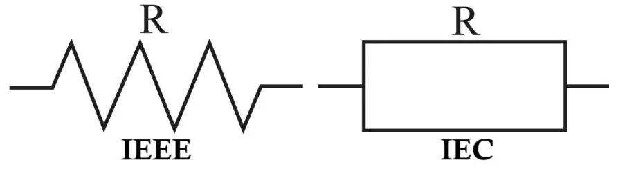
- Zig-zag symbol (ANSI standard) – commonly used in American schematics
- Rectangular symbol (IEC standard) – widely used in international and industrial documentation
The symbol does not explicitly indicate “thick film”; the resistor type is specified in the bill of materials (BOM) or component datasheet.
Related Articles:
- Metal Film Resistor Construction, Working, Types and Applications
- Carbon Composition Resistor Construction, Working & Applications
- Carbon Film Resistor Construction, Working, Types & Applications
- Types of Resistors with Symbol, Classification and Applications
Construction of Thick Film Resistor
The construction of a thick film resistor is based on screen-printing technology over a ceramic substrate.
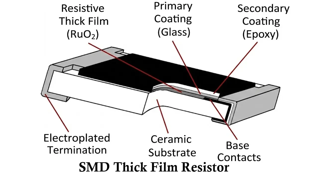
Main construction layers
- Ceramic Substrate
- Usually made from alumina (Al₂O₃)
- Provides mechanical strength, electrical insulation, and good thermal stability
- Resistive Thick Film Layer
- A paste composed of:
- Conductive metal oxides (e.g., ruthenium oxide)
- Glass frit (acts as binder)
- Organic solvents
- Screen-printed onto the substrate
- Thickness typically ranges from 10 to 50 micrometers
- A paste composed of:
- Firing Process
- The printed substrate is fired in a kiln at 800–1000°C
- Organic binders burn off
- Glass frit melts and bonds the resistive material to the substrate
- Trimming
- Laser trimming is used to precisely adjust resistance value
- Improves tolerance accuracy
- Protective Overcoat
- Epoxy or glass coating
- Protects against moisture, dust, and mechanical damage
- Termination Contacts
- Silver, nickel, or tin-plated terminations
- Enable soldering onto PCBs (especially in SMD packages)
Working of Thick Film Resistor
The working of a thick film resistor is based on controlled electrical resistance through a composite resistive path.
- The resistive layer contains conductive particles dispersed in a glass matrix
- Electrical current flows through a network of microscopic conductive paths
- Resistance depends on:
- Composition of resistive paste
- Thickness and width of printed film
- Distance between terminations
When voltage is applied:
- Electrons move through the resistive film
- Energy is dissipated as heat according to Joule’s law
- The ceramic substrate helps spread and dissipate heat efficiently
Characteristics of Thick Film Resistor
Electrical characteristics
- Resistance range
- Typically, from 1 Ω to 10 MΩ
- Extended ranges possible with specialized formulations
- Tolerance
- Common values: ±1%, ±2%, ±5%, ±10%
- Less precise than thin film resistors
- Temperature Coefficient of Resistance (TCR)
- Typically ±100 to ±1000 ppm/°C
- Higher than thin film resistors
- Voltage coefficient
- Resistance may change slightly with applied voltage
- More pronounced than in metal film resistors
Thermal characteristics
- Moderate power dissipation capability
- Ceramic substrate provides good heat resistance
- Resistance may drift at high operating temperatures
Mechanical characteristics
- High mechanical strength
- Excellent resistance to vibration and shock
- Suitable for harsh industrial environments
How to Read Value of Thick Film Resistors
THT Thick Film Resistors
They use the color band coding system.
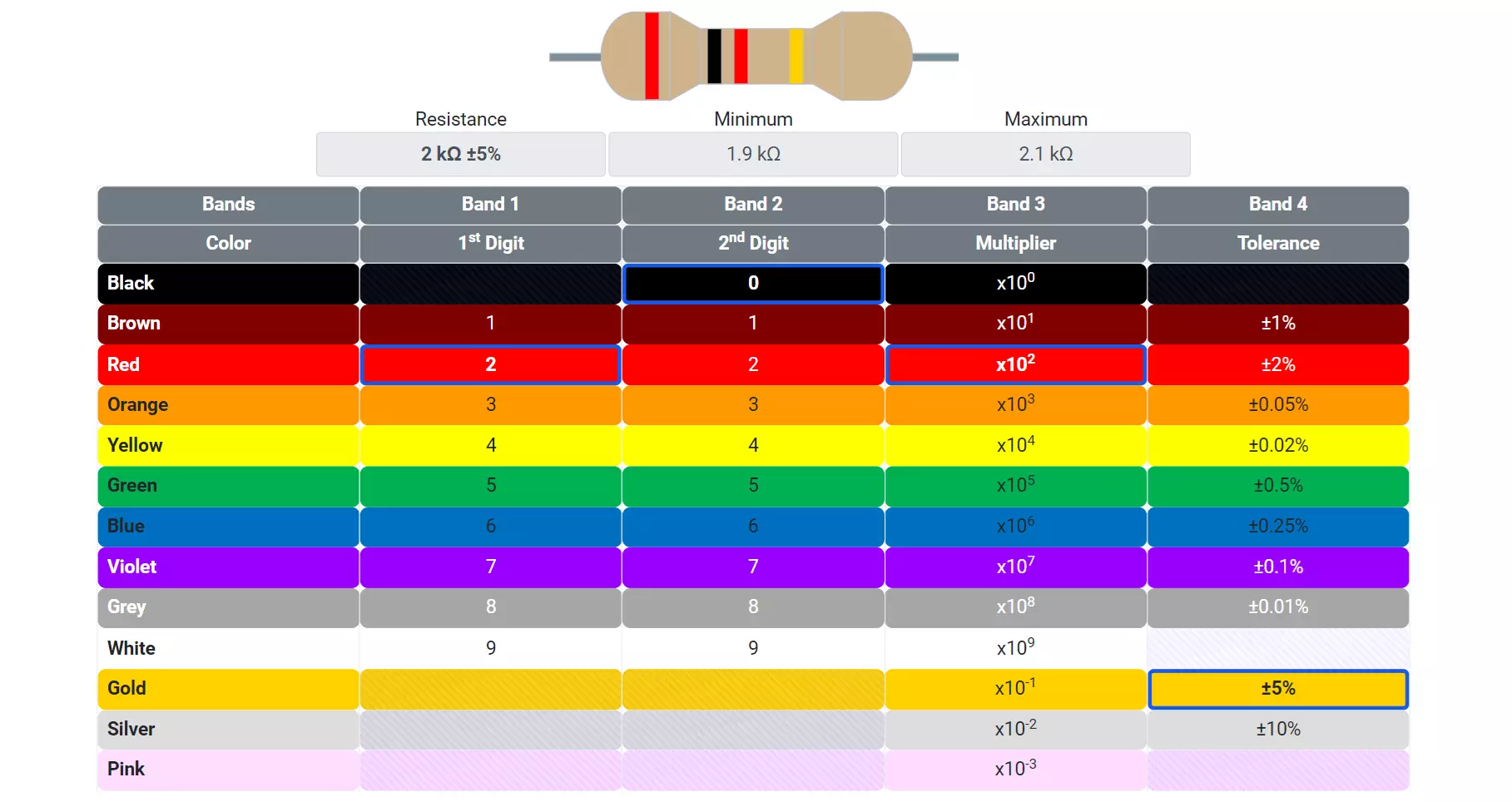
- First two or three bands: significant digits
- Next band: multiplier
- Final band: tolerance
Five-Band Color Code
| Band | Meaning | Example (Brown-Black-Black-Red-Brown) |
|---|---|---|
| 1 | First digit | Brown = 1 |
| 2 | Second digit | Black = 0 |
| 3 | Third digit | Black = 0 |
| 4 | Multiplier (×10ⁿ) | Red = ×100 |
| 5 | Tolerance (%) | Brown = ±1% |
Resistance = (100 × 100) = 10,000 Ω or 10 kΩ ±1%
SMD Thick Film Resistors
SMD thick film resistors use numeric codes.
- 3-digit code:
- First two digits: significant figures
- Third digit: multiplier
- Example: 472 → 47 × 10² = 4.7 kΩ
- 4-digit code:
- First three digits: significant figures
- Fourth digit: multiplier
- Example: 1001 → 100 × 10¹ = 1 kΩ
- Low-ohm resistors may use R notation: 4R7 = 4.7 Ω
You can use this SMD resistor code calculator to find exact value of SMD resistor.
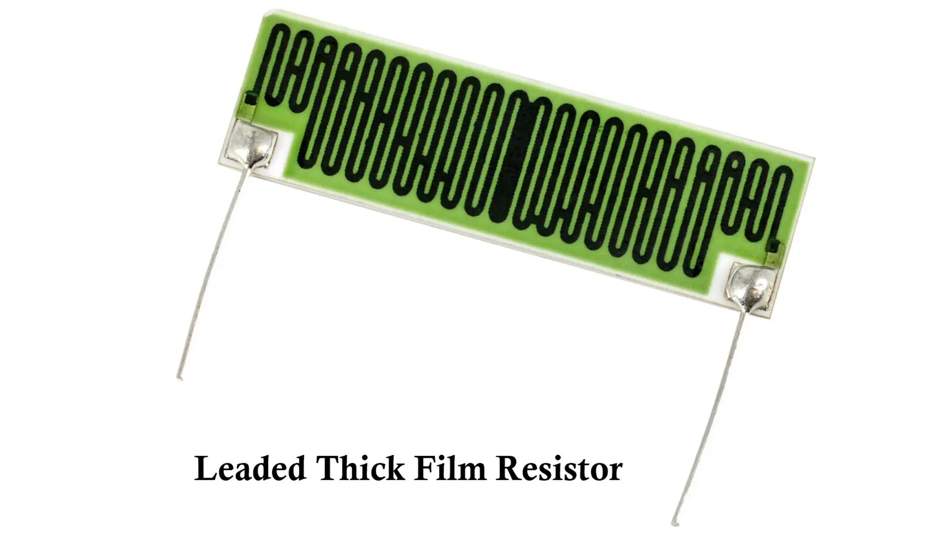
Types of Thick Film Resistors
- Fixed Thick Film Resistors
- Most common type
- Available in axial and SMD packages
- Used for general-purpose applications
- Chip Thick Film Resistors
- Surface-mount design (SMD)
- Sizes: 0402, 0603, 0805, 1206, etc.
- Dominant type in modern electronics
- High-Voltage Thick Film Resistors
- Designed with longer resistive paths
- Used in SMPS and high-voltage circuits
- High-Power Thick Film Resistors
- Larger ceramic substrates
- Better heat dissipation capability
- Thick Film Resistor Networks
- Multiple resistors on a single substrate
- Used for pull-up/pull-down arrays and DACs
Selection Criteria for Thick Film Resistors
When selecting a thick film resistor, consider the following parameters:
- Resistance value: Ensure correct nominal resistance for the circuit
- Tolerance: Choose tighter tolerance for precision circuits
- Power rating:
- Common values: 1/16 W, 1/10 W, 1/8 W, 1/4 W
- Always derate for reliability
- TCR: Lower TCR preferred for temperature-sensitive applications
- Package size: SMD size affects power dissipation and PCB layout
- Operating voltage: Ensure voltage rating exceeds maximum circuit voltage
- Environmental conditions: Moisture, vibration, and temperature range
Advantages of Thick Film Resistors
- Low manufacturing cost
- Suitable for mass production
- Wide resistance range
- High mechanical durability
- Good compatibility with SMD technology
- Stable performance for general-purpose applications
Disadvantages of Thick Film Resistors
- Lower precision compared to thin film and metal film resistors
- Higher noise levels
- Higher temperature coefficient
- Greater resistance drift over time
- Not ideal for high-accuracy analog circuits
Applications of Thick Film Resistors
Thick film resistors are used in almost every category of electronic equipment:
- Consumer electronics (TVs, audio systems, chargers)
- Power supplies and SMPS circuits
- Automotive electronics
- Industrial control systems
- IoT and embedded systems
- Digital logic circuits
- Pull-up and pull-down networks
- Voltage dividers in non-critical applications
Summary Table: Thick Film Resistor
| Parameter | Description |
|---|---|
| Resistor Type | Fixed resistor |
| Manufacturing Method | Screen-printed thick film |
| Substrate | Alumina ceramic |
| Resistance Range | 1 Ω to 10 MΩ |
| Tolerance | ±1% to ±10% |
| TCR | ±100 to ±1000 ppm/°C |
| Noise Level | Moderate |
| Cost | Low |
| Precision | Medium |
| Common Packages | Axial, 0402–1206 SMD |
| Typical Applications | General-purpose electronics |
Conclusion
Thick film resistors strike a practical balance between cost, durability, and performance, making them the backbone of modern electronic manufacturing. While they cannot match the precision of thin film or metal film resistors, their versatility and affordability ensure their continued dominance in consumer, industrial, and automotive electronics.
Types of Resistors with Symbol, Classification and Applications
Metal Film Resistor Construction, Working, Types and Applications
Types of Capacitors with Symbol, Classification and Applications
Different Types of Inductors Their Properties and Applications
