Silicon Controlled Rectifier (SCR) is one of the oldest four-layer solid-state power device. SCR has the highest power handling capacity in comparison with other semiconductor devices. It is a member of SCR family, it was invented in 1957.
- It is a four-layer device with three terminals that are accessible to the user namely anode, cathode, and gate.
- SCR is a latching device, we can turn on SCR using the gate terminal, but we can’t turn off SCR using the same gate terminal.
- In the case of the Shockley diode, the user can’t control the break overvoltage. In the case of silicon-controlled rectifier (SCR), it is possible to control the breakover voltage.
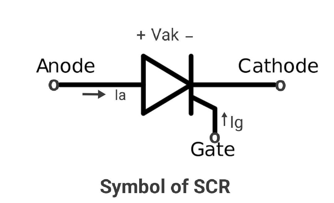
Symbol of Silicon Controlled Rectifier SCR:
The symbol of SCR is shown in the figure. It can be seen that SCR is a thyristor with a third terminal known as gate. The direction of anode current, the voltage across the thyristor, and the direction of the conventional gate current are shown in the figure.
The Internal Structure of SCR:
The construction of SCR is as shown in the figure.
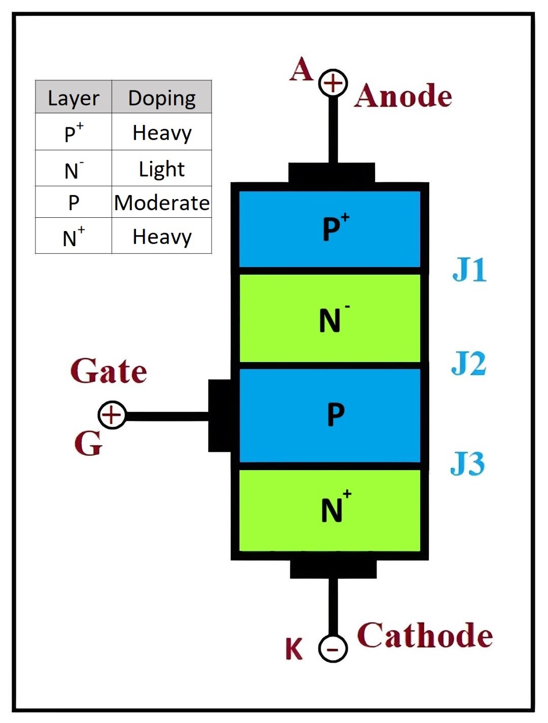
Construction of SCR Silicon Controlled Rectifier:
SCR is a four-layer PNPN device, with three terminals available to the user namely anode, cathode, and gate. The gate terminal is a controlling terminal that can turn on the device whenever required. We can use SCR as a controlled device.
The Silicon Controlled Rectifier (SCR) is a four-layer, three-terminal semiconductor device consisting of alternating layers of p-type and n-type materials, forming a PNPN or NPNP structure. There are three junctions in SCR namely J1, J2, and J3 to turn on SCR the anode must be at the highest positive potential then cathode. This means SCR should be in forward bias mode. The junctions are created through alloying or diffusion processes.
Terminals and Structure:
- Anode (A): Positively charged electrode where conventional current enters the device.
- Cathode (K): Negatively charged electrode where conventional current exits the device.
- Gate (G): Control terminal that regulates the current flow between the Anode and Cathode.
Typical PNPN structure of an SCR:
- The Anode is connected to the first p-type layer.
- The Cathode is connected to the last n-type layer.
- The Gate is connected to the second p-type layer, which is closer to the Cathode.
The outer p-type and n-type layers are heavily doped, while the middle p-type and n-type layers are lightly doped. Silicon is used as the base material for these layers due to its low leakage current compared to germanium.
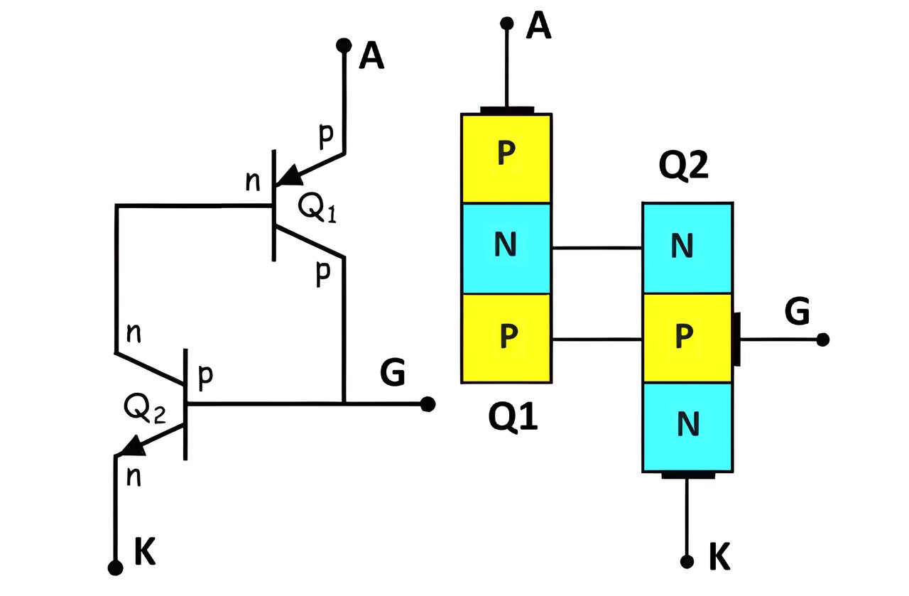
Internal Structure and Two-Transistor Model:
An SCR can be visualized as a combination of two transistors:
PNP Transistor (Q1): The Anode acts as the emitter.
NPN Transistor (Q2): The Cathode acts as the emitter.
The internal connections are as follows:
- The base of Q1 is connected to the collector of Q2.
- The collector of Q1 is connected to the base of Q2.
- The Gate terminal is connected to the base of Q2.
This arrangement is known as the two-transistor model, which provides an insightful way to understand the operation of an SCR.
Working of SCR Two-Transistor Model:
- Without Gate Current: Initially, both transistors are off because there is no gate current. This keeps the SCR in a high-resistance state (OFF state).
- With Gate Current: When a small positive gate current is applied to the base of Q2, it turns on the NPN transistor (Q2), which in turn causes the PNP transistor (Q1) to turn on. This regenerative feedback quickly brings both transistors into saturation, allowing a large current to flow from the Anode to the Cathode, turning the SCR into the ON state.
The direction of anode and gate current is conventional current directions. SCR is a unidirectional device, and the gate current can only be positive the gate current can flow in one direction, into the gate terminal.
Working of Silicon Controlled Rectifier SCR:
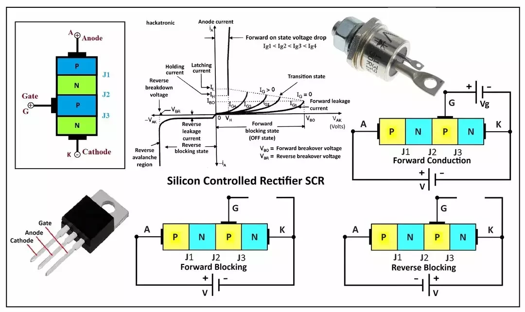
The working of an SCR (Silicon Controlled Rectifier) can be comprehended by analyzing its behavior in three distinct modes: Reverse Blocking Mode, Forward Blocking Mode, and Forward Conduction Mode. Here is a detailed explanation of each mode:
Reverse Blocking Mode of SCR:
In the reverse blocking mode, the SCR is reverse biased by connecting its anode (A) to the negative terminal and its cathode (K) to the positive terminal of the power supply. In this configuration:
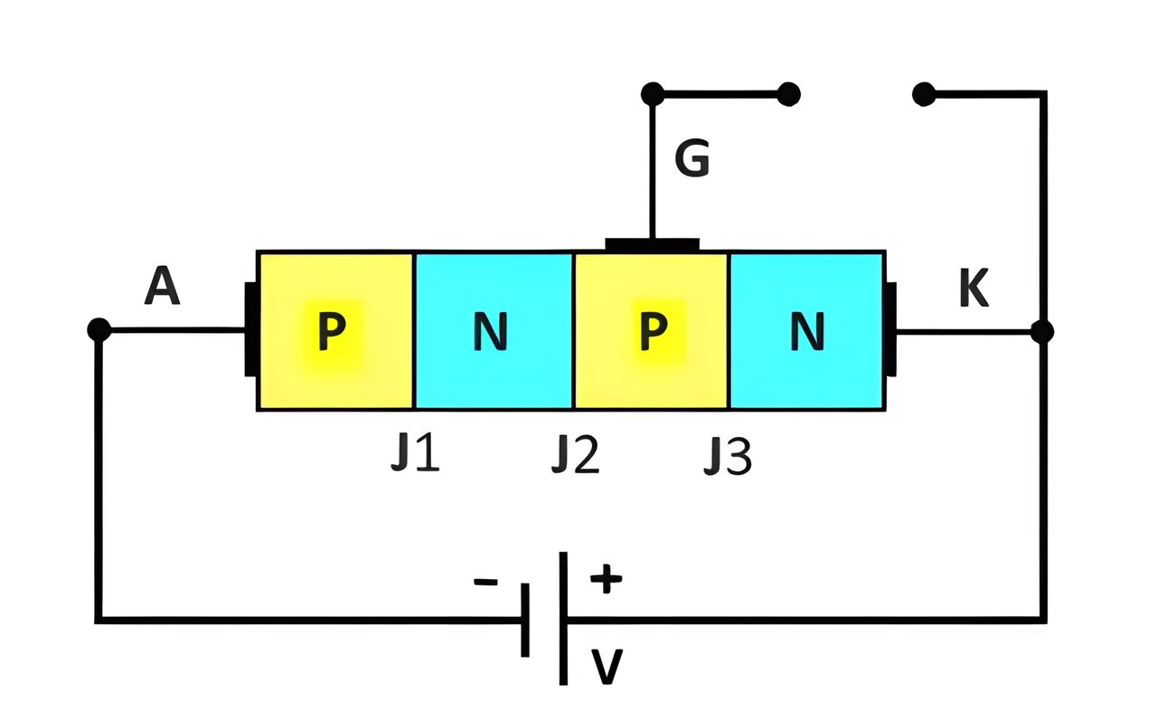
- Junctions J1 and J3 are reverse biased.
- Junction J2 remains forward biased.
Since J1 and J3 are reverse biased, they prevent current from flowing through the SCR, similar to the behavior of a reverse-biased diode. The only current flowing is a tiny reverse saturation current, which is negligible. However, if the reverse voltage exceeds a certain threshold (reverse breakdown voltage), the SCR will experience reverse breakdown, allowing a large reverse current to flow and potentially damaging the device.
Forward Blocking Mode of SCR:
In the forward blocking mode, the SCR is forward biased by connecting the anode (A) to the positive terminal and the cathode (K) to the negative terminal of the power supply. Under this condition:
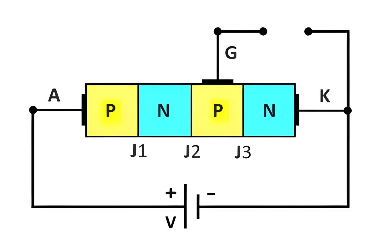
- Junctions J1 and J3 are forward biased.
- Junction J2 is reverse biased.
Although J1 and J3 allow current to flow, J2 prevents it due to its reverse-biased state. Consequently, the SCR remains in a high-impedance state, blocking any significant current, except for a small leakage current (forward leakage current). This mode is represented by the portion of the characteristic curve where the current remains low despite increasing forward voltage.
Forward Conduction Mode of SCR:
The SCR enters the forward conduction mode when it is made to conduct. This can be achieved in two ways:
Break Over Voltage (VB): By increasing the anode-cathode voltage beyond a specific threshold called the breakover voltage (VB), the reverse-biased junction J2 breaks down. This results in a large current flow through the SCR.
Gate Triggering: By applying a positive voltage to the gate terminal (G) relative to the cathode (K), the SCR can be triggered into conduction without requiring the voltage to reach the breakover level. The gate current induces carriers in the J2 junction, making it conductive and allowing current to flow from anode to cathode.
Once triggered, the SCR continues to conduct even if the gate current is removed, provided the anode-cathode current remains above a certain level called the holding current. This behavior is depicted by the steep rise in current in the characteristic curve once the SCR switches to the conduction mode, indicated by the pink curve in the figure.
Summary
- Reverse Blocking Mode: SCR blocks current flow, behaving like a reverse-biased diode.
- Forward Blocking Mode: SCR is forward biased but still blocks current due to the reverse-biased junction J2.
- Forward Conduction Mode: SCR conducts current either by exceeding breakover voltage or by gate triggering.
Understanding these modes is crucial for effectively utilizing SCRs in applications like controlled rectification, voltage regulation, and motor control.
SCR VI Characteristics Graph:
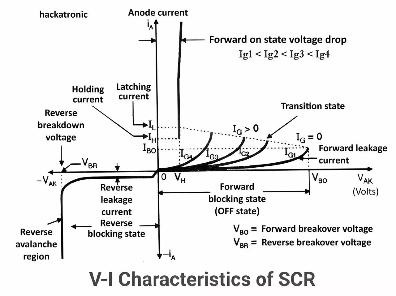
The V-I characteristics of an SCR can be visualized in a graph where the voltage (V) is plotted on the x-axis and the current (I) is plotted on the y-axis. The operation of SCR can be studied by two conditions first with gate current and second without the gate current. Here’s a simplified explanation of the graph’s regions:
Forward Bias Mode Operation:
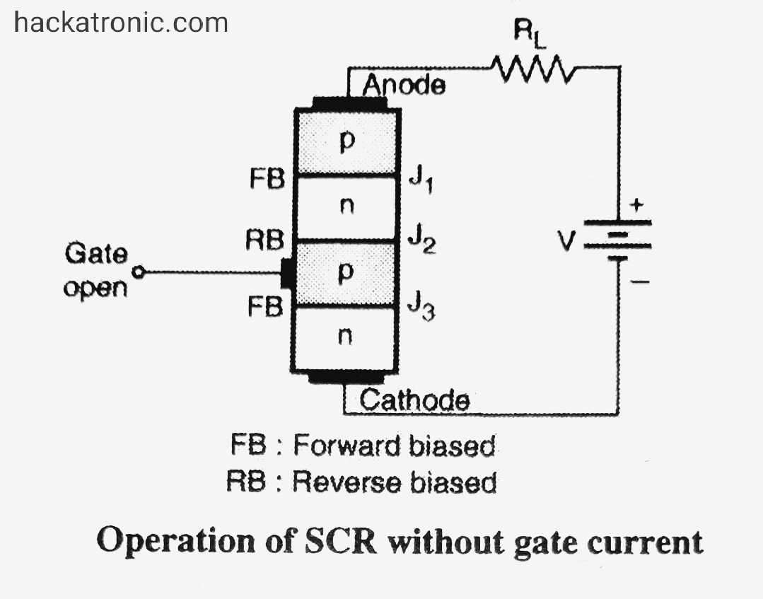
Operation of SCR without gate current:
- The SCR is biased in a forward direction by applying a positive voltage to the anode with respect to the cathode, the gate terminal is left open so that If = 0.
- Out of three junctions, the junction J1 and J3 are forward biased and junction J2 is reverse biased. No current flow through the SCR and the entire applied voltage appears across the junction J2.
- As the anode to cathode voltage is increased the voltage across junction J2 increases.
- After a certain voltage the junctions J2 will break down and SCR will start conducting this voltage is called a forward breakover voltage Vbo.
- Thus, it is possible to turn on an SCR without any gate current by exceeding its forward voltage beyond Vbo.
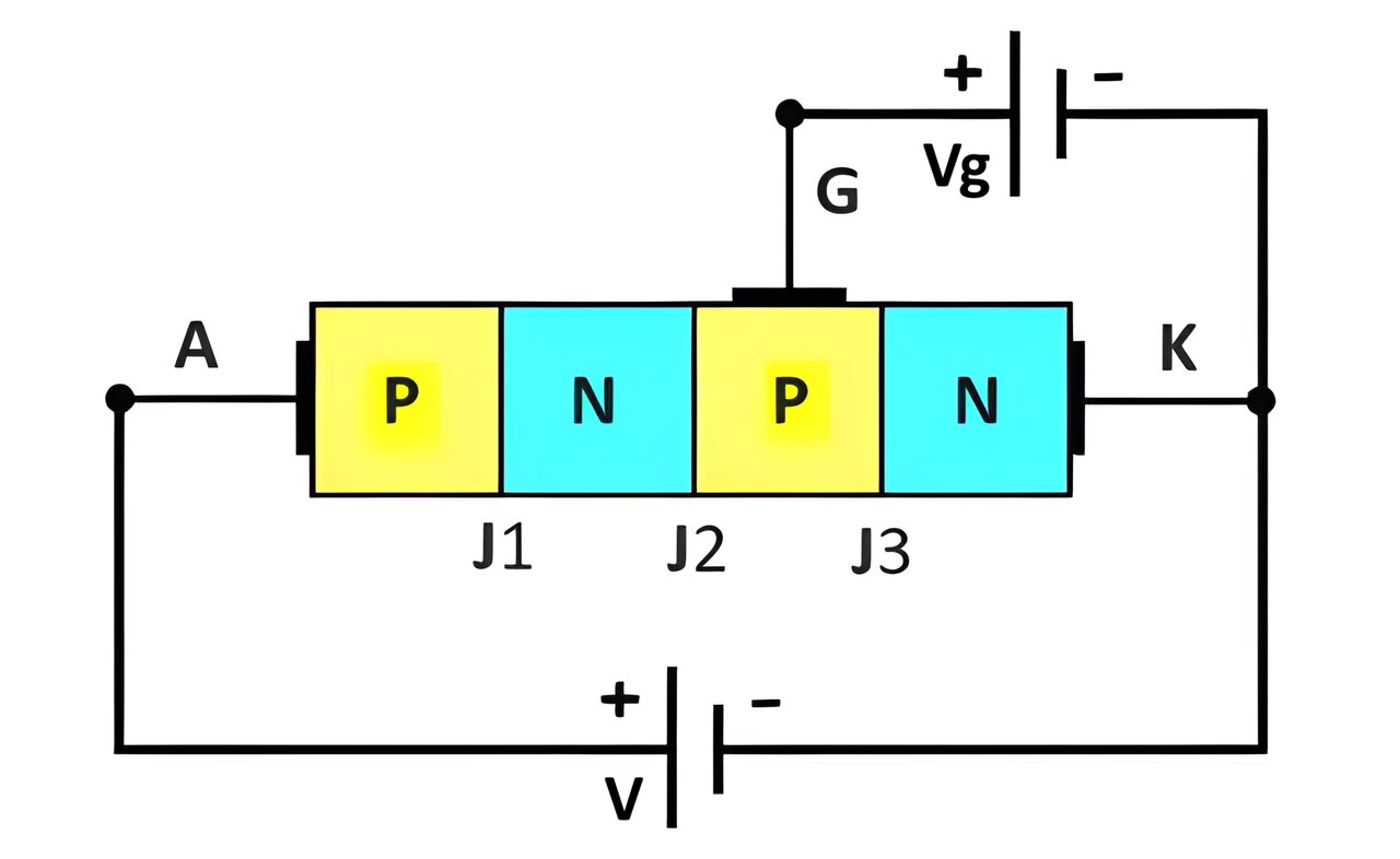
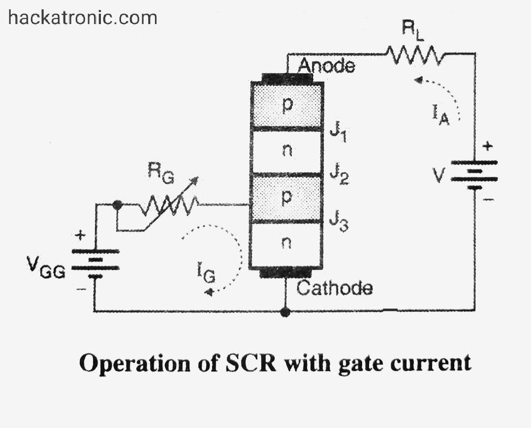
Operation with gate current:
- The SCR is forward biased and the gate-cathode junction J2 is also forward biased using an external power source.
- The gate current Ig starts flowing due to forward bias this current can be adjusted by resistance Rg.
- The value of the gate current will decide the breakover voltage of SCR. As Ig increases, breakover voltage decreases that will turn on SCR at a lower and lower voltage.
Forward Blocking Region:
- Low current flow.
- Voltage increases up to the forward breakover voltage (V_BO).
Breakover Point:
- The point where the SCR switches from blocking to conducting.
- Triggered by a gate pulse or by exceeding the forward breakover voltage.
Forward Conducting Region:
- High current flow.
- Low voltage drop across the SCR.
- The current is primarily limited by the external load and circuit.
Reverse Bias Mode Operation:
- If the anode to cathode voltage is negative the SCR is reverse biased. Junction J1 and J3 are reverse biased and a very small leakage current flows through the device due to thermally generated minority carrier electrons and holes.
- If reverse voltage increases above the reverse breakdown voltage the SCR will turn on due to the avalanche breakdown effect.
- A large reverse current flow through the device and a large reverse voltage appears across it. The SCR can get damaged due to excessive power dissipation. Hence reverse breakdown should be avoided.
Reverse Blocking Region:
- Low current flow (leakage current).
- Voltage increases up to the reverse breakdown voltage (V_BR).
Detailed Breakdown of the Graph:
- A: Forward Blocking Region (OFF state) – Voltage increases with minimal current.
- B: Breakover Point – SCR switches to the conducting state upon gate triggering or exceeding V_BO.
- C: Forward Conducting Region (ON state) – High current with low voltage drop.
- D: Reverse Blocking Region (OFF state) – Voltage increases with minimal reverse current until V_BR.
Summary:
The V-I characteristics of an SCR illustrate how the device operates in different states. Understanding these characteristics is crucial for effectively utilizing SCRs in various applications, such as controlling power flow, managing motor speed, and protecting circuits.
