A differentiator opamp is an opamp configuration that produces a differentiated version of the signal applied to its input terminal. This process is exactly the opposite of integration. by interchanging the positions of components in an integrator circuit we can get a differentiator circuit.
Here we’re going to discuss two types of differentiator circuit:
- Ideal differentiator
- Practical differentiator
Ideal opamp as differentiator circuit:
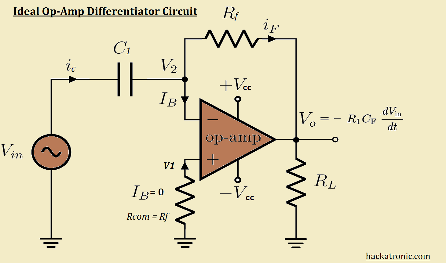
Circuit for ideal differentiator is as shown in the figure:
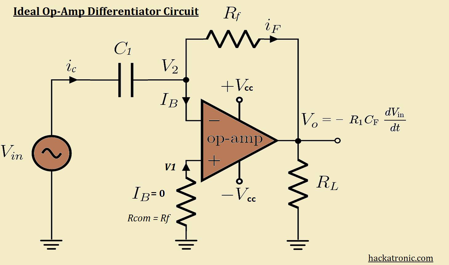
- this circuit can perform the mathematical operation of differentiation on the input signal. The output is a differentiation of input signal.
- The differentiator circuit can be constructed by interchanging the input resistance R1 and feedback capacitor Cf of an integrating amplifier.
- the resistance Rcom connected from non-inverting terminal to ground provides bias compensation.
Expression for the output voltage:
- By considering an ideal op-amp we get, V2 = 0, IB = 0
- From Kirchhoff’s current law we can write,
Ic = Ib + If
- Since Ib = 0 the above equation becomes, Ic = If
- We know that,
Ic = C [dVc/dt]
- The voltage across C1 is given by,
Vc = Vin - V2
- Substituting this in the above equation we get,
If = C1[d/dt (Vin - V2)
- Now let us obtain the expression for current If.
If = [ V2 - Vo ] / Rf
- But Ic and If are equal because Ib = 0 as shown hence from above equations we get,
C1 [d/dt(Vin - V2) = [V2 - Vo] / Rf
- By using the concept of virtual ground we can say V1 = V2 = 0.
- Substituting V2 and V1 in above equation we get,
C1[d/dt(Vin)] = - Vo/ Rf
- On rearranging we get,
Vo = - Rc C1 [d/dt (Vin)]..............(a)
- Thus the output is – Rf C1 times the derivative of the input signal.
- The -Ve sign indicates 180° please shift between input and output signals.
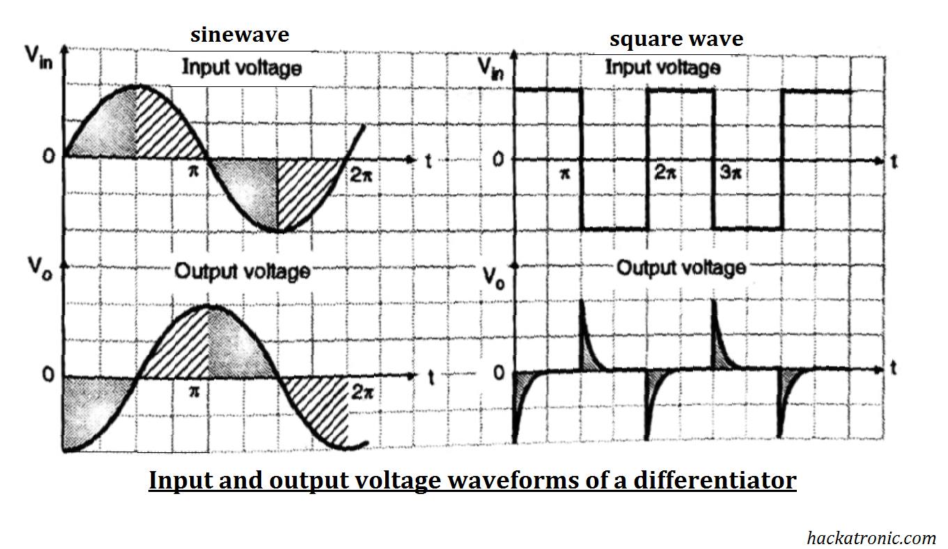
Input and output voltage waveforms:
- From expression assuming Rf * Cf = 1 we get,
Vo = - [ d/dt ] Vin
- The above equation says that the rate of change of input voltage with respect to time.
- When the input voltage is constant meaning that the rate of change of input voltage is zero, the output voltage is zero.
- But as soon as the input voltage changes from zero to a constant voltage there is a large rate of change of voltage at that instant of time.
- Therefore, a large output voltage is produced at t = 0 and this voltage is negative as the Differentiator is an inverting differentiator. The output voltage is a negative spike as shown in the figure.
Output voltage for a square wave input:
- A square wave is actually made of many step signals.
- Thus, the output voltage is in the form of spikes corresponding to the rising and falling edge of the square wave.
- The output voltage is zero when the input becomes constant.
Output voltage for a sine wave input:
- Let the input signal be
Vin = A sin (ωt)
- Assuming that Rf * Cf = 1 differentiating above equation we get,
Vo = - A/ω cos (ωt)
- Hence the output voltage is an inverse cosine wave out of phase with respect to the input voltage.
Here are some problems with basic differentiator circuit:
- The gain of a differentiator circuit is (Rf / Xc). As Xc1 decreases with an increase in frequency, the gain increases with an increase in frequency.
- This increase in gain at high frequency will make the circuit unstable. Also, the input impedance which is equal to Xc1 reduces with an increase in frequency.
- This makes the circuit very much susceptible to high-frequency noise. The amplified noise at the output can completely override the output signal.
Practical Opamp as Differentiator:
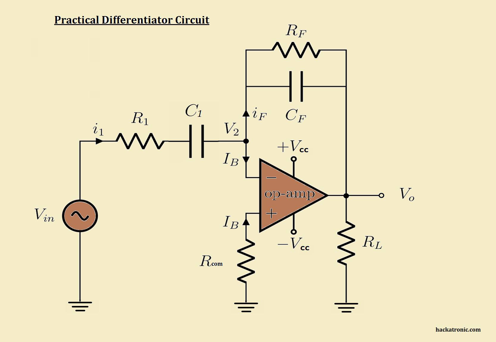
A practical differentiator circuit is slightly different from the ideal circuit. It has an input resistance and a feedback capacitor.
Advantages of active differentiator:
- Sharp output.
- Gain can be controlled.
- Sharp frequency response.
Disadvantages of active differentiator:
- This circuit is widely affected by noise.
- It is less stable therefore there is a possibility of oscillations.
- Gain increases with an increase in frequency.
- The output is affected by the parameter of op-amp.
Applications of differentiator:
- In the PID controllers.
- As a high pass filter.
- In the wave shaping circuit to generate narrow pulses corresponding to any sharp change in the input signal.
Difference between opamp integrator and Differentiator:
| Sr, No. | parameters | opamp integrator | opamp Differentiator |
|---|---|---|---|
| 1 | Output Voltage | Vo = – 1/R1*Cf ∫[Vin dt ] + c | Vo = – Rf*C1 d/dt Vin |
| 2 | Feedback element | Capacitor | Resistor |
| 3 | Gain | Decrease with the increase in frequency | Increase with the increase in frequency |
| 4 | Acts as | Low pass filter | High pass filter |
| 5 | Effect of noise | Less | More |
| 6 | Stability | More | Less |
| 7 | Applications | A/D converters, PID controllers, filters, waveform generator. | Logic circuit, pulse shaping filters. |
OP-AMP tutorial:
-
Opamp as Differentiator (active differentiator)
-
OP AMP integrator
-
Voltage Follower OPAMP or buffer Amplifier
-
Non Inverting Amplifier (OPAMPs)
-
Inverting amplifier (OPAMPs)
-
741 Op Amp, First Operational Amplifier IC
-
What is operational amplifier? basics concepts
-
Automatic Battery Charger circuit using LM358 OP-AMP
×

Tenine güneş değmeyenlere selam olsun. By Engin.
Instagram takipçi hilesi her saat ücretsiz 100 takipçi kazan!