In this blog you can find opamp tutorial and circuits like differentiator integrator, summing amplifier and many more circuit. Operational amplifier basics detailed explanation and working of each circuit.
An operational amplifier is a DC-coupled high-gain electronic voltage amplifier amplifier that has high gain, differential input, high input resistance, and low output resistance.
There are mainly two types of opams amplifiers inverting amplifiers and others one is non inverting amplifier.
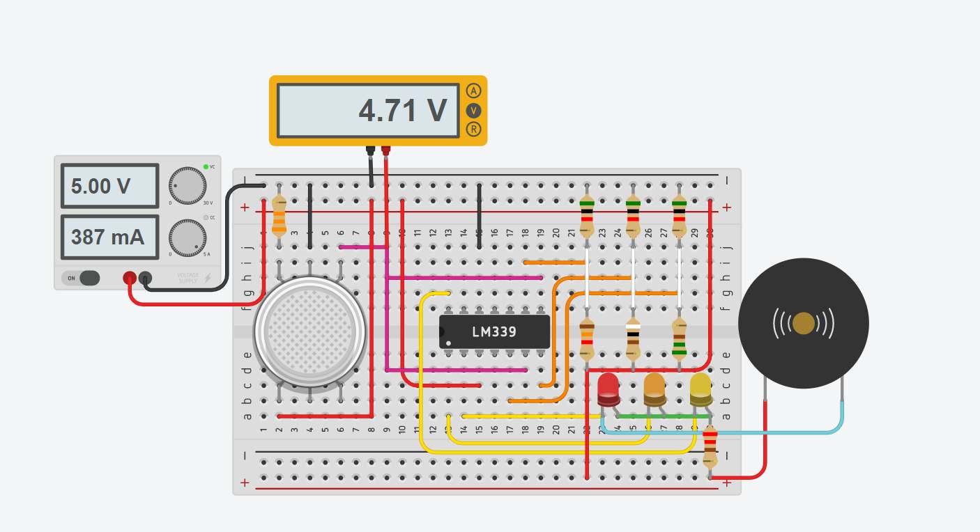
In this project, we will use the MQ2 Gas sensor circuit to detect Methane, Butane, LPG, Smoke which is released into the environment at the time of the gas leak. MQ2 Gas sensor circuit diagram is as shown in the figure. MQ2 gas sensor can sense butane, LPG, Smoke, Alcohol, Propane, Hydrogen, Methane and Carbon […]
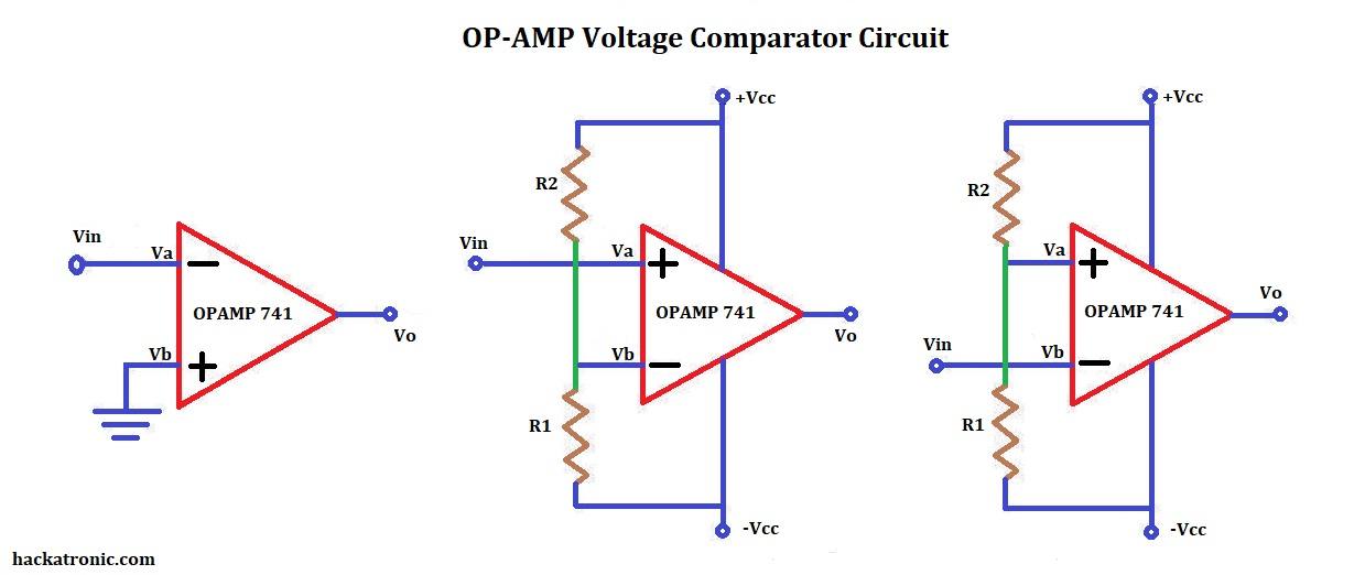
A voltage comparator is a circuit which compares the voltages at its input terminals and switches the output to either high or low depending upon which input was high. making a voltage comparator using transistors and other components is quite difficult and makes no sense because we have OPAMPs. We can use 741, LM311, LM324, […]
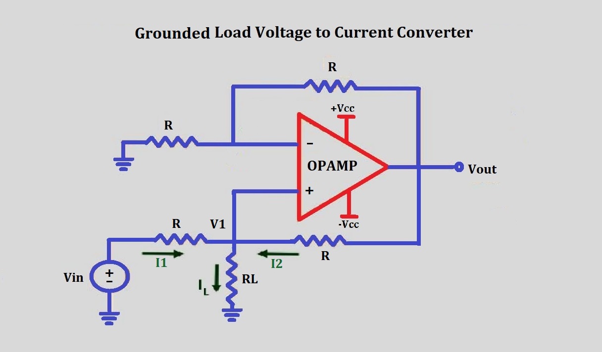
Voltage to current converter is mostly used to transmit signals over a long distance to a control circuit. The most important reason behind it is that while traveling a long distance due to the internal resistance of the wire the voltage gets reduces. if there is a very small signal then it may get lost. […]
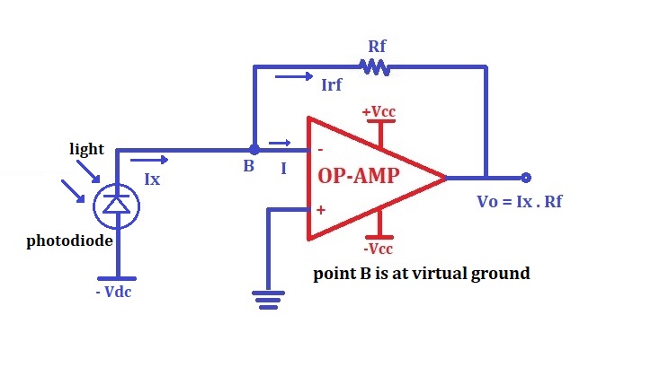
A current to voltage converter circuit produces output voltage with respect to input current. An I to V converter is used to convert varying current into equivalent output voltage. This circuit is very much useful when the measuring instrument can measure only voltages not the current and we want to measure the output current. The […]
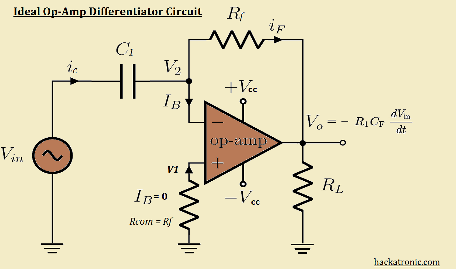
A differentiator opamp is an opamp configuration that produces a differentiated version of the signal applied to its input terminal. This process is exactly the opposite of integration. by interchanging the positions of components in an integrator circuit we can get a differentiator circuit. Here we’re going to discuss two types of differentiator circuit: Ideal […]
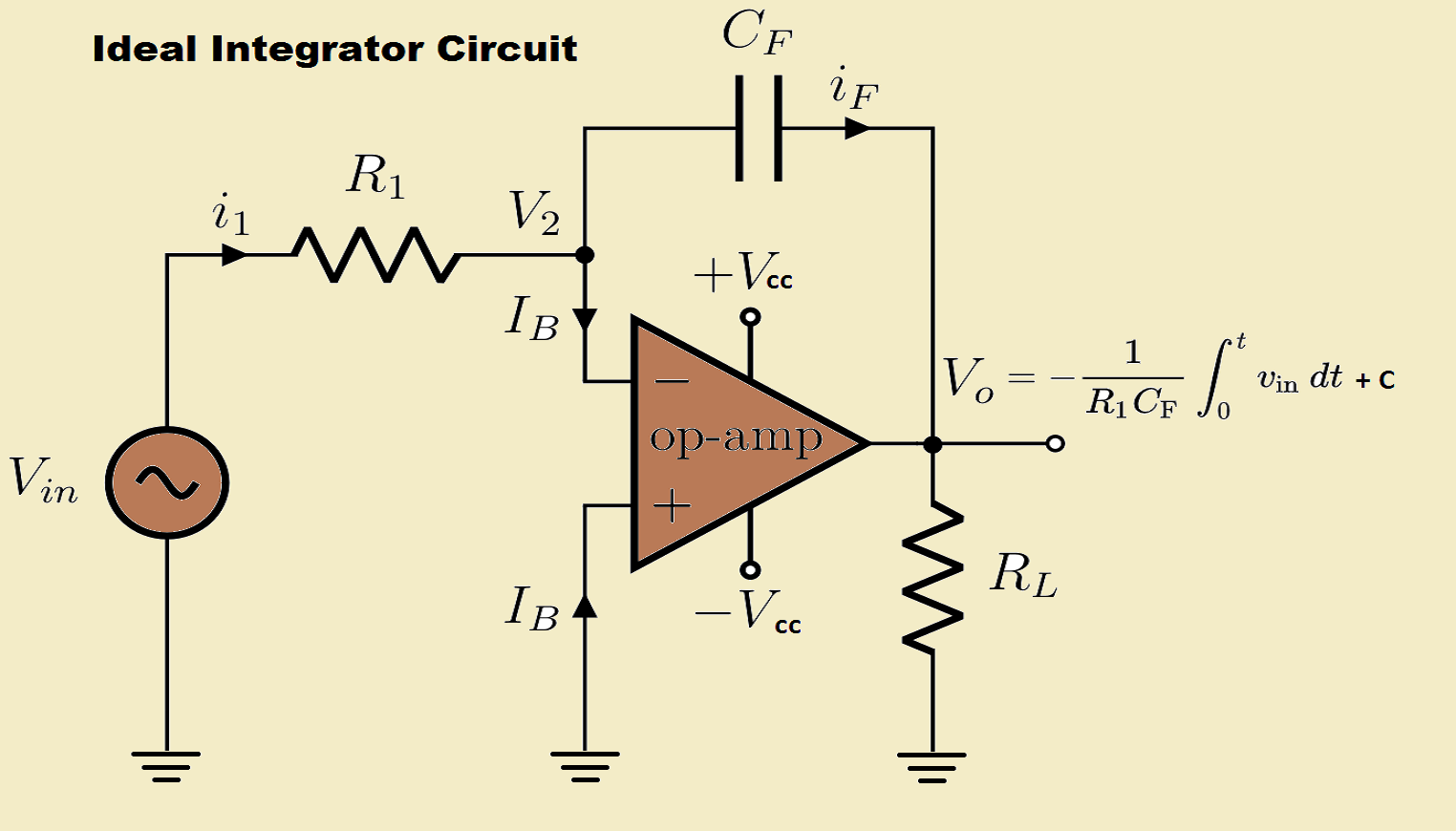
The circuit in which output voltage waveform is an integration of the input signal is called as an integrator or op-amp integrator or integrating amplifier. The output voltage is proportional to the amplitude and duration of the input signal. Ideal op amp Integrator Circuit: The above circuit is obtained by replacing the feedback resistor RF […]