Want to build a simple and effective water level indicator circuit at home? In this guide, we’ll show you how to make a water level indicator using BC547 transistors, a few LEDs, and a buzzer. This is a fun and educational mini project for students and hobbyists interested in basic electronics.
Concepts Covered: Transistor Switching and Water Conductivity
Basics of Transistor Switch
Before starting, it’s helpful to have a basic understanding of how a transistor works, especially the NPN-type like the BC547. If you’re new to this, consider watching a beginner-friendly video or reading up on transistor basics.
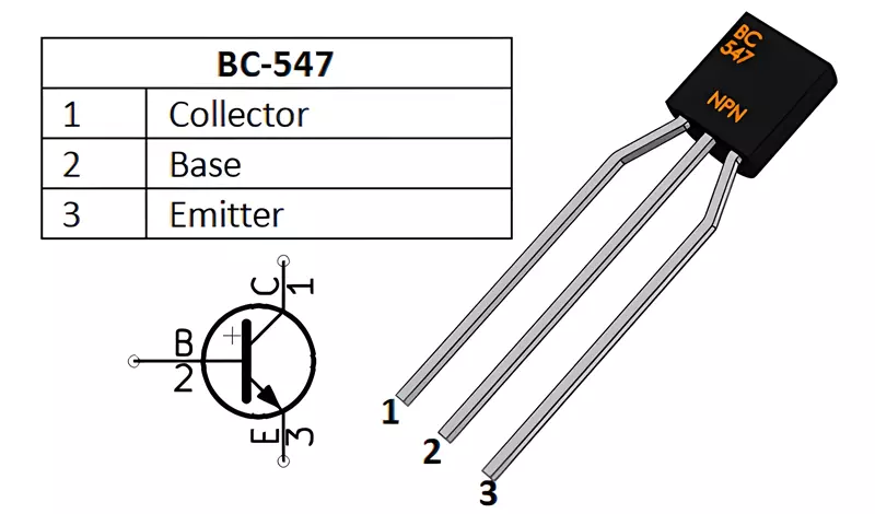
A transistor is a semiconductor device used to amplify or switch electronic signals. In this project, we use the BC547 NPN Bipolar Junction Transistor (BJT). It has three terminals: Emitter (E), Base (B), Collector (C)
Switching Behavior
We are using the transistor in switching mode, which means:
- When the base receives a small positive current, it allows a larger current to flow from collector to emitter.
- If there’s no current at the base, the transistor remains off (open circuit).
Why Water Conducts Current
Water isn’t a perfect conductor, but due to dissolved minerals and impurities, it can conduct a tiny amount of current (in microamperes). That small current is enough to trigger the base of the transistor and turn it ON.
Water Level Indicator Circuit using BC547 Transistor
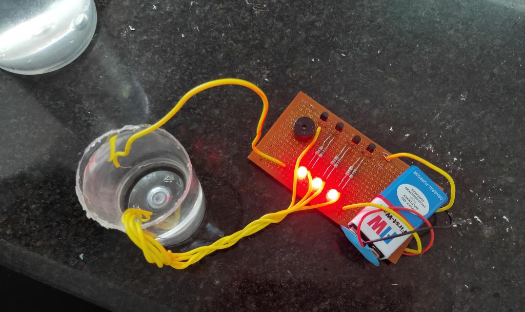
Here is a simple BC547 transistor-based water level indicator circuit with 3 LEDs, 6 220Ω, Buzzer and a 9V battery.
Components Required
| Component | Quantity |
|---|---|
| BC547 NPN Transistor | 4 |
| LEDs (Red, Yellow, Green) | 3 |
| 220Ω Resistors | 6 |
| Buzzer (5V or 9V) | 1 |
| Breadboard or PCB | 1 |
| Single-strand wires | As needed |
| 9V or 5V Battery | 1 |
| Soldering Kit (optional for PCB setup) | 1 |
Water Level Indicator Circuit Diagram
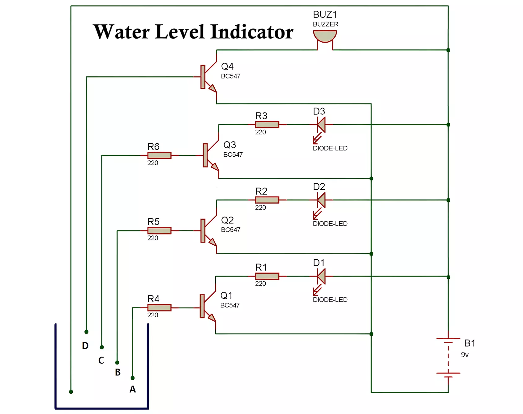
Construction Overview
- Q1, Q2, Q3, Q4: These are your four BC547 transistors.
- The emitters of all transistors are connected to the negative terminal (-) of the battery.
- The collectors are connected to the anode of LEDs or buzzer through a 220Ω resistor.
- Q1 → Red LED
- Q2 → Yellow LED
- Q3 → Green LED
- Q4 → Buzzer
- The bases of the transistors are each connected through a 220Ω resistor to probes dipped at different levels inside a water container.
- The positive terminal (+) of the battery is also inserted into the water tank via a separate wire or probe.
How It Works
- Initially, when the water is below the probes, the circuit is OFF—no current flows through the transistors.
- As the water level rises and touches the first base probe (connected to Q1), a tiny current flows into the base of Q1 due to water conductivity.
- This turns Q1 ON, allowing current to flow from collector to emitter—lighting the Red LED.
- As water rises further, it touches the next probe, turning Q2 ON, lighting the Yellow LED.
- Next level activates Q3 → Green LED.
- When the water reaches the topmost probe connected to Q4, it switches ON the buzzer, providing an audible alert that the tank is full.
Water Level Indicator Circuit by IC ULN2003
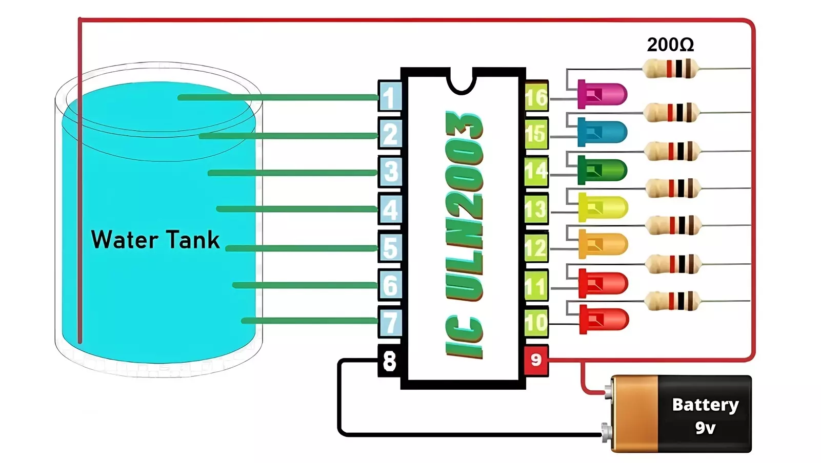
If you don’t want to use transistors and prefer a simpler circuit with more LEDs, here’s a basic Water Level Indicator using a ULN2003 IC, 7 LEDs, 200Ω resistors, and a 9V battery. This setup visually displays the water level in a tank, with LEDs lighting up progressively as the level rises. See the datasheet of ULN2003 IC.
Components Required:
- ULN2003 IC – 1
- 200Ω Resistors – 7
- LEDs – 7 (any color you prefer)
- 9V Battery – 1
- Battery Clip – 1
- Water Tank with Probes (Metal Wires) – 8 (1 common + 7 level sensors)
- Breadboard or PCB and jumper wires
Circuit Diagram
Circuit Connections:
1. Probes:
- Place 8 metal wires in the tank:
- 1 wire at the bottom: Common
- 7 wires placed at increasing heights: Level1 to Level7
2. ULN2003 IC:
- Pin 1–7: Inputs (connect to the probe wires)
- Pin 8: GND (connect to negative of battery)
- Pin 9: VCC (connect to positive of battery)
- Pin 10–16: Outputs (connect to LEDs)
3. LEDs:
- Cathode of each LED → ULN2003 output pins 10–16
- Anode of each LED → One leg of 200Ω resistor
- Other leg of resistor → +9V battery
LED Mapping:
| Tank Level | Input Pin (ULN2003) | Output Pin | LED Position |
|---|---|---|---|
| Level 1 (lowest) | Pin 1 | Pin 16 | LED1 |
| Level 2 | Pin 2 | Pin 15 | LED2 |
| Level 3 | Pin 3 | Pin 14 | LED3 |
| Level 4 | Pin 4 | Pin 13 | LED4 |
| Level 5 | Pin 5 | Pin 12 | LED5 |
| Level 6 | Pin 6 | Pin 11 | LED6 |
| Level 7 (highest) | Pin 7 | Pin 10 | LED7 |
4. Power:
- +9V from battery → Resistors (LED anodes)
- Battery negative terminal → ULN2003 GND (pin 8)
Working of The Circuit:
- When water touches a sensor probe, a small current flows from the 9V through the water to the ULN2003 input.
- The ULN2003 acts as a current sink, grounding the cathodes of the LEDs when the input goes HIGH.
- ULN2003 input goes HIGH → Output pin sinks current → LED turns ON.
- The more water in the tank, the more LEDs light up from bottom to top.
Tips and Improvements
- Ensure the water probes are made from corrosion-resistant material like stainless steel or copper.
- For permanent installation, insulate connections and seal them properly.
- You can increase the number of levels by adding more transistors and LEDs.
- Also, you can control a motor pump by implementing a relay controlled from transistor switch.
Advantages of Water Level Indicator
- Low Cost: Uses inexpensive and readily available components.
- Easy to Build: Ideal for beginners and students; no need for microcontrollers or programming.
- Simple Design: Straightforward working principle based on transistor switching.
- Expandable: You can add more transistors and LEDs to indicate more water levels.
- Battery Operated: Can run on 9V or 5V batteries, making it portable and independent of mains power.
Disadvantages of Water Level Indicator
- Limited Accuracy: Water conductivity can vary with impurities, possibly affecting switching consistency.
- Corrosion of Probes: Prolonged exposure to water can corrode bare metal probes if not properly protected.
- No Digital Display: This basic model doesn’t show exact level percentages—just level indications with LEDs.
- Manual Calibration: Probe placement and sensitivity require manual adjustment and testing.
- Not Suitable for Purified Water: Pure water has very low conductivity and may not trigger the base current.
Applications of Water Level Indicator
- Overhead Water Tank Monitoring in homes and apartments.
- School and College Science Projects to demonstrate transistor switching and water conductivity.
- Smart Farming or Irrigation Systems, as a part of water management setups.
- Industrial Storage Tanks (only for basic level detection; not for hazardous or high-precision use).
- DIY Electronics Learning Kits and prototyping.
Conclusion
Building a water level indicator using BC547 transistors is a great introduction to practical electronics. It helps demonstrate how basic components like transistors can be used in real-world sensing and control applications.
Despite its simplicity, this project teaches essential concepts such as conductivity, transistor switching, and basic circuit design. It’s perfect for students, DIY enthusiasts, and anyone looking to explore how electronic sensors can solve everyday problems.
With a little effort, you can even upgrade this project into a more advanced system using comparators, ICs like ULN2003, or even microcontrollers for digital display and automation.
Astable Multivibrator Circuit Diagram, Working and Applications
3 Simple IR Proximity Sensor Circuits with Working & Applications

if i reverse the led connection then only it is working as per video it is not that means