In this blog you will see how to make Flashing LED with 555 timer. 555 IC can work in three modes Astable, Monostable, and Bistable, out of which we will be using Astable mode of working.
Watch this video to understand better
Overview:
In astable mode 555 timer continuously oscillates between 0 and 1 ( on to off). By using a Potentiometer and a suitable capacitor you can control the frequency and duty cycle of of output wave at pin number 3 of 555.
Components required:
1.) 555 timer IC -1
2.) Capacitors 100 microfarad and 10 nanofarad
3.) 1 k resistor -1(R1)
4.) 10k potentiometer (R2)
5.) 330 resistors -2
6.) LED lights (w, RBG) of any color -2
7.) Battery 5V to 15V
8.) PCB or breadboard
9.) Wires
Circuit Diagram:
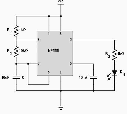
How to Connect?
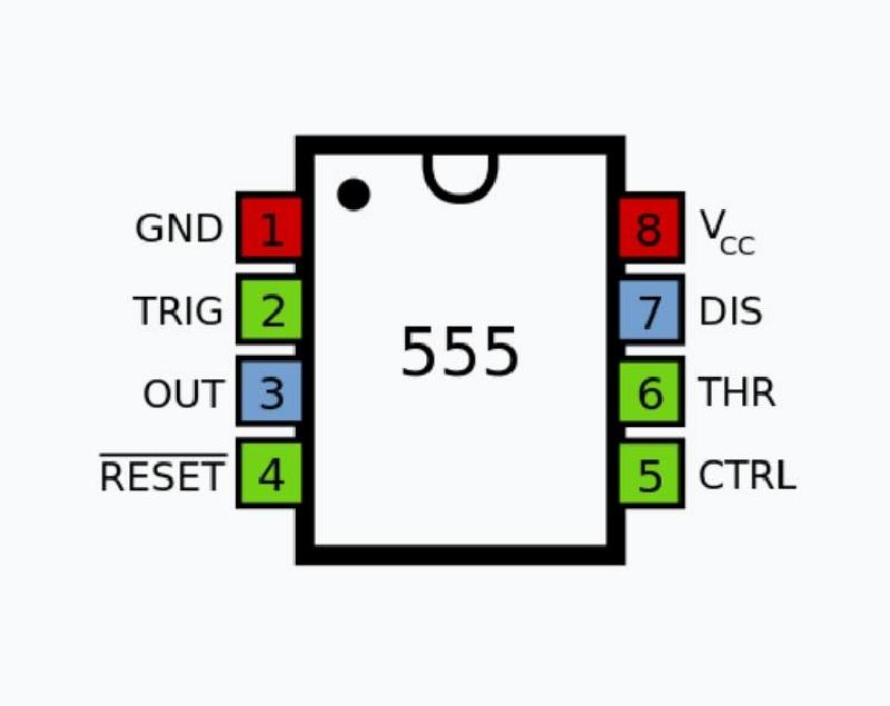
Place the IC on breadboard, pin number 1 starts from a dot on the IC. Now
1.) Connect pin number 1 to ground and pin number 8 to Vcc.
2.) Connect 1k resistance between pin 8 and 7.
3.) Short pin number 2(trigger) and 6(threshold), now connect +ve terminal of 100 microfarad capacitor to 2 and 6, ground the -ve terminal of capacitor.
4.) Connect the 10 k potentiometer between pin number 6(threshold) and 7(discharge).
5.) Connect 10 nanofarad capacitor to pin 5 or you can leave it open.
6.) Connect +ve terminal of LEDs to pin number 3 via 330 ohm resistor and ground the -ve terminal of LEDs.
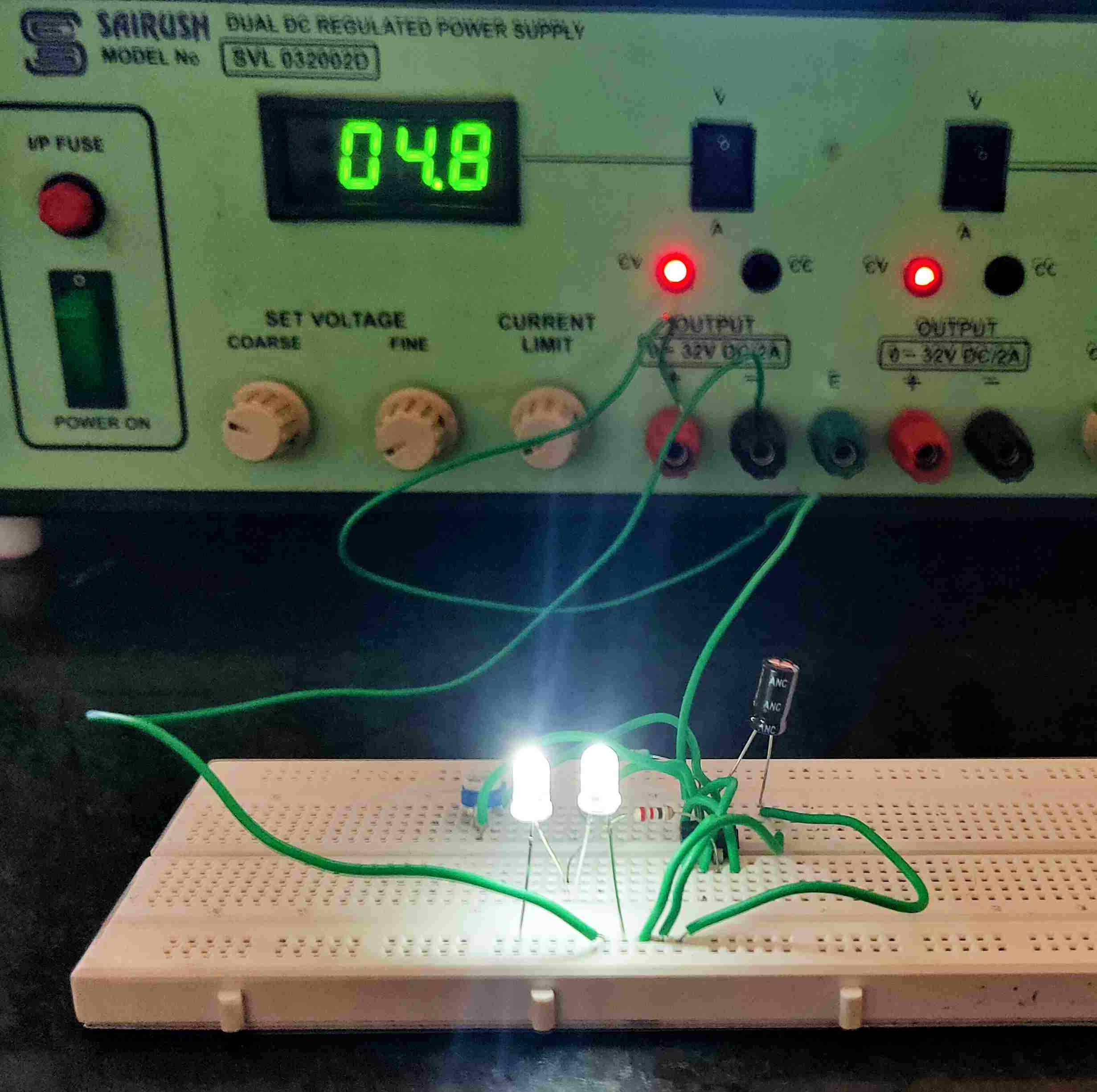
Working of Flashing LED with 555 timer:
As shown in the circuit diagram the Flashing LED with 555 timer works in Astable mode it continuously oscillates between high and low. There are two comparators in the IC which compare the voltage at 100 microfarad capacitor and voltage divider and make the output of IC 0 or 1.
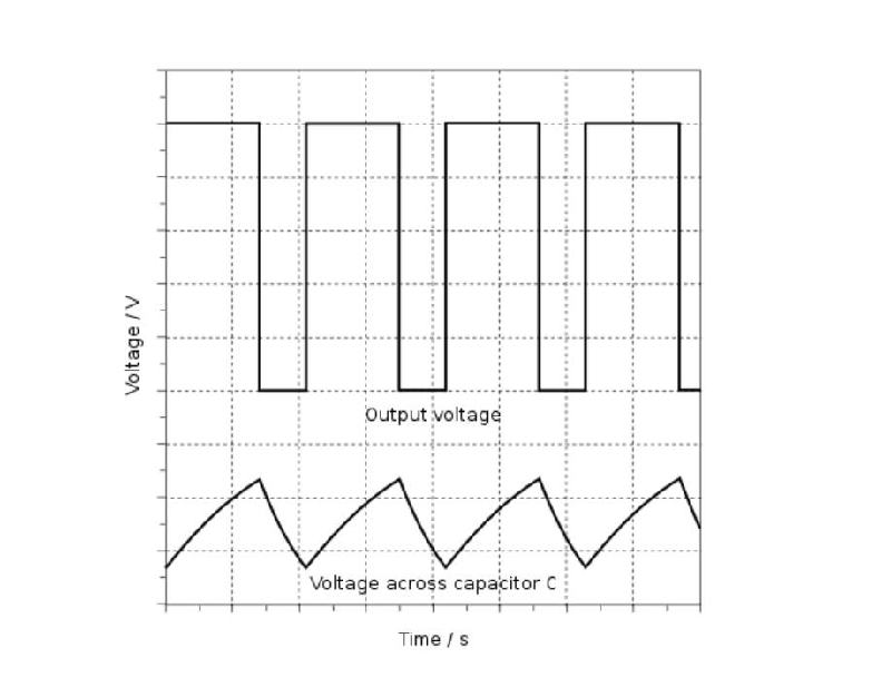
When Voltage at capacitor is less than 1/3 of the Vcc the output of IC is high(1) and it remains high upto when the capacitors voltage reaches 2/3 of the supply voltage. When Voltage at capacitor becomes greater than 2/3of the Vcc the output of IC becomes low (0) and capacitor start to discharging. The output of IC remains low upto when the capacitors Reaches 1/3 of Vcc after that it again becomes High (1). That’s how the 555 timer works in Astable mode.
You can make PWM by controlling the duty cycle of output rectangular wave by connecting 10k potentiometer between pin 6 and 7. The onn time and off time of LEDs depends on the values of resistor R1 and R2. To understand more precisely read this blog.
