This is an adjustable over-current and Short circuit protection using LM358 OPAMP. In this article, we will see how you can make short circuit protection using LM358 OPAMP.
A short circuit occurs when the current flowing in a circuit bypasses the load and flows from a path having the least or zero resistance. We can make a short circuit by connecting positive and negative terminals of the power supply (Here we are talking about DC power only). When a short circuit occurs heavy current flows through the circuit. This current has no medium to dissipate electrical power hence it causes a lot of heat and even fire. So we must prevent short circuits. We can do this by using short circuit protection circuit.
The OPAMP switches output load using a MOSFET, we have used IRF540N N channel MOSFET. I recommend you use a heatsink if the load current is larger than 500mA.
To power the circuit we have used an LM7809 voltage regulator. This is a 9V 1A linear voltage regulator with a wide input voltage.
What are the components required for Short circuit protection:
- 12V to 30V power supply
- LM7809 9V voltage regulator.
- IRF540N n-channel MOSFET.
- Heatsink for MOSFET.
- LM358D dual OPAMP IC.
- 100uF/25V electrolytic capacitor.
- 50k potentiometer.
- R1 1Ω 2W resistor.
- R2 1KΩ resistor.
- R3 1MΩ resistor.
- R4 100kΩ resistor.
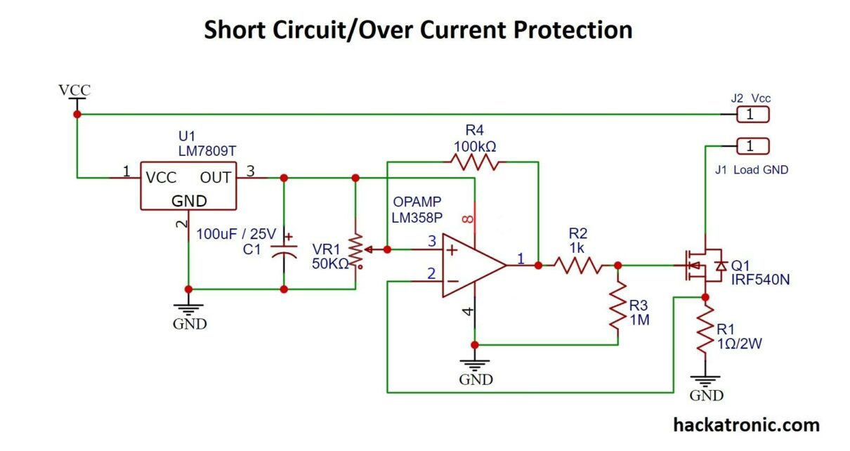
Circuit Explanation:
LM7809 gives a 9V output at PIN 3, a 100uF filter capacitor is used to filter out any fluctuation and make the output smooth.
LM358 is a general purposes operational amplifier IC it has two OPAMPs but we are using only one. PIN 3 of OPAMP connects to the variable terminal of the potentiometer. pin 1 is the output terminal of OPAMP, it is connected to the gate of MOSFET IRF540N. The drain terminal of MOSFET connects to the ground of load whereas the source terminal is connected to the ground. The reference voltage at resistor R1 is given to Pin 2 of the OPAMP. R4 is a feedback resistance connecting input and output.

Working Of Short Circuit Protection Using LM358 OPAMP:
This circuit aims to disconnect the load as soon as a short circuit or over current occurs by switching the MOSFET Q1. So how the circuit will detect overcurrent? This is done by shunt resistor R1, which is a 1Ω having a 2-watt rating. This method is known as Shunt Resistor Current Sensing.
Current flows from load to drain terminal of MOSFET and then to ground via 1Ω resistor. As per Ohm’s Law V = I x R, Where V is voltage I is current and R is resistance. Depending on the load current shunt resistor produces a voltage drop across it. Assuming that current flowing through the load resistor is 1A voltage produced across 1Ω resistor is 1V. By comparing this voltage with a reference voltage using OPAMP we will switch the MOSFET to ON and OFF state.
The voltage drop produced across the 1Ω shunt resistor is applied to the inverting terminal of the operational amplifier IC at pin 2. This voltage is compared with the reference voltage set at PIN 3 of the operational amplifier. You can adjust the reference voltage by rotating the potentiometer. When the voltage at inverting terminal of OPAMP becomes more than the non-inverting terminal output at terminal 1 becomes Low and MOSFET switches to OFF state the load gets disconnected and thus an overcurrent or short circuit is protected.
We have used 100kΩ resistor R4 as feedback from output to input. This feedback makes the circuit more stable and reduces false tripping. Resistor R2 is the gate driving resistance and R3 is the Gate pull-down resistance of MOSFET.
Recommendations Regarding Short circuit protection:
- Use proper heatsink.
- RC snubber circuit is very useful in reducing EMI effects.
- Use a low wattage shunt resistor, since high current will cause a lot of heat production.
- You can use a current sense amplifier to accurately sense current.

I wanted to learn about the circuit used in lab bench power supplies.. is this the one? will it work with heavy loads like 15A or 600W?
It should work if you have good components
Hi, how can this circuit be incorporated with SG3525 PWM iC for inverter? I mean how do you connect it with the IC?
This circuit will connect to battery.
Dear Mr. Singh
I have a 0-48V 0-10A variable power supply,
1- Is this circuit capable of handling 10A?
2- Where exactly should the output of my power supply be connected?
Thanks for your reply
IRF540N can handle 10A, change 1Ω resistor to lower value since it will generate more heat at 10A.
Connect the output of power supply between J1 and J2.
Thanks for your quick reply, so J1 & J2 are in parallel with the power supply output probes?
No, it’s in series