Here are the basic electronics tutorial circuits for beginners. You can find here tutorials on operational amplifiers (opamp), transistor, MOSFETs, 555 timer IC, audio amplifiers and many more.
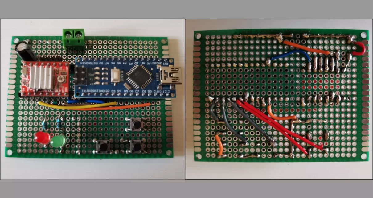
The word “proto” refers to the essential initial stage of electronic invention. An electronic circuit design’s physical form is represented by a prototype circuit board or proto-circuit board. Engineers can test and improve their ideas with this first construction, transforming abstract thoughts into practical realities. Consider a proto HDI PCB to be the prelude to the big […]
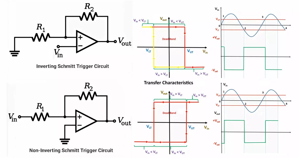
The Schmitt trigger is a bistable circuit widely used in digital and analog applications. It is primarily employed for signal conditioning, converting noisy, analog signals into clean, digital ones, and plays a critical role in eliminating the ambiguity associated with fluctuating or noisy input signals. A distinctive feature of the Schmitt trigger is the concept […]
Let’s learn about binary numbers and Binary conversion of Decimal, Hexadecimal and Octal numbers. In this digital world, every blink of a screen, every swipe of a smartphone, and each byte of data moving online depend on one simple concept binary. It is a universal language that allows computers and other digital devices to communicate […]
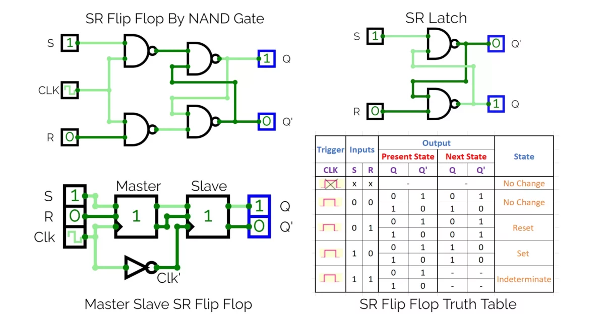
Let’s see SR latch and explore SR flip flop truth table, with its working, advantages, limitations and applications. The SR flip-flop, also known as the Set-Reset flip-flop, is a fundamental building block in digital electronics used for storing a single bit of data. This type of flip-flop has two inputs labeled S (Set) and R […]
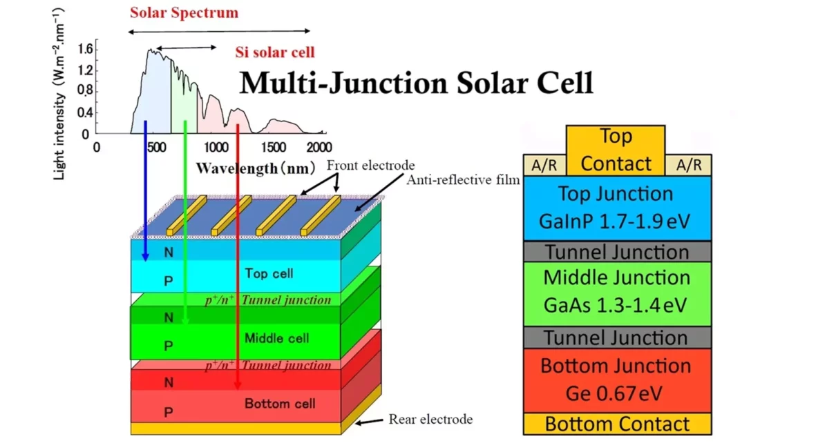
This article delves into the detailed workings of multijunction solar cells, their structure, advantages over conventional solar cells, and their potential impact on the future of renewable energy. Multijunction solar cells represent a significant leap in solar technology, enhancing energy conversion efficiency to 40% as compared to conventional single junction solar cells (20% average). Their […]
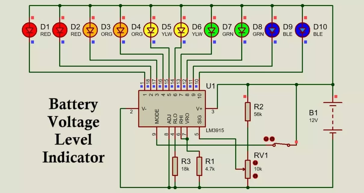
In this article, you will learn to build LM3915 battery voltage level indicator. The LM3915 is a popular integrated circuit (IC) used in projects that require visual feedback on voltage levels. It’s widely applied in devices like battery monitors, audio level meters, and power supply indicators. This IC lights up a series of LEDs to show […]