In the following article, we will explore the voltage divider circuit and its operation. With that, we will let you know how a voltage divider calculator helps anyone determine voltage across the circuits and even compare two or more circuits.
Stay focused to learn better!
Definition of Voltage Divider:
“A voltage divider is a simple electronic circuit that converts a high voltage to a lower voltage based on the potential of resistors connected.”
Diagram of Voltage divider:

A Schematic Circuit Diagram:
To understand the functionality of a voltage divider, you need to look at the following circuit figure:
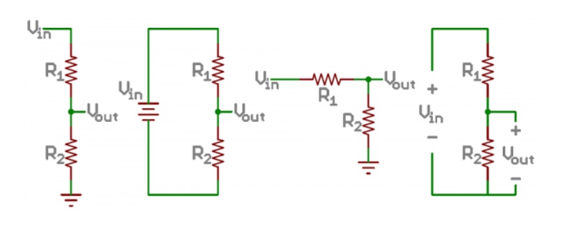
In the above picture, there are three different circuits. All of them are voltage dividers. With that, although these circuits look different, analyzing them will let you know that they are the same.
In a voltage divider, you just have to connect a battery source with a series of two resistances. The value of the resistances can be different. Also, the output voltage will always depend upon the overall opposition installed in the circuit.
A better way to determine voltage divider calculations is to use a voltage divider calculator by calculatored.com. The tool instantly lets you know the resulting voltage value that depends upon the resistors connected in series.
Voltage Divider Equation:
The voltage divider formula states the clear direct relationship between the following circuit parameters:
- The input voltage
- Output voltage
- The ratio of two resistors (Parallel combination value)
The equation used by the voltage divider calculator is as follows:
Vout = Vin*(R2/R1+R2)
Generalizations to Consider:
To make a voltage divider circuit easily, you should learn to convert the basic voltage divider circuit equation to its equivalent forms, which include:
Number 01:
If both resistors have the same value, then the output voltage value is reduced to half of the supply voltage.
if R1 = R2: Vout = Vin*(R/2R) = Vin2
Number 02:
if R2>>R1: Vout = Vin*(R2R2) = Vin
if R2 << R1: Vout = Vin*0R1 = 0
Exploring Circuit:
To understand the functioning of the voltage divider circuit, consider the following scenario A.
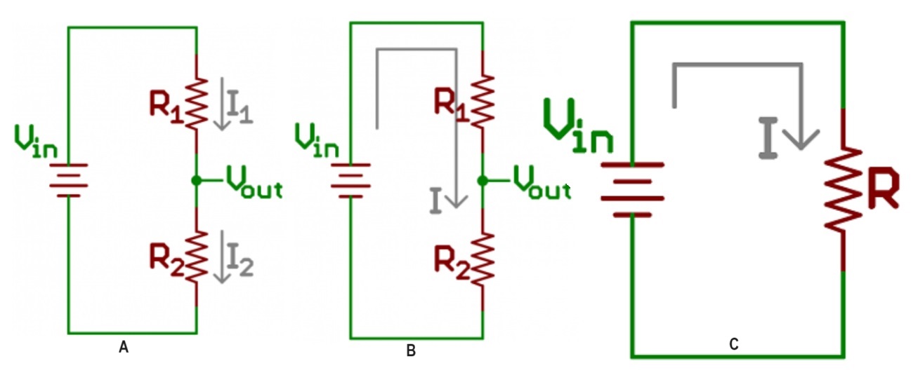
In this image, we have two currents I_1 and I_2 that are flowing through their respective resistances R_1 and R_2.
So if we want to determine the output voltage with R_1, R_2, and Vin known, we can apply the Ohms law to figure that out. The reason is that two resistors are in series, so their accumulated effect will be the same.
V2 = I2*R2
From this expression, we can easily calculate R_2 value. But what about I_2 value? To get its value, we assume that I_2 = I_1. this makes the above circuit looks like B.
As R_1 and R_2 are in series, they are considered as one resistor, equivalent to the below expression:
R = R1+R2
So the simplified version of the above circuit is shown in C.
By applying Ohms law, we get the following values for the current:
I = Vin*(R1+R2)
As both the currents are equal to one another, the final equation of the voltage divider circuit becomes:
Vout = R2*(Vin/R1+R2)
Last Words:
In the article, we have thoroughly discussed the voltage divider circuit. If you still face issue in determining the voltage across such circuits, you can use the voltage divider calculator. The tool will help you compare different circuits as well in less time.
