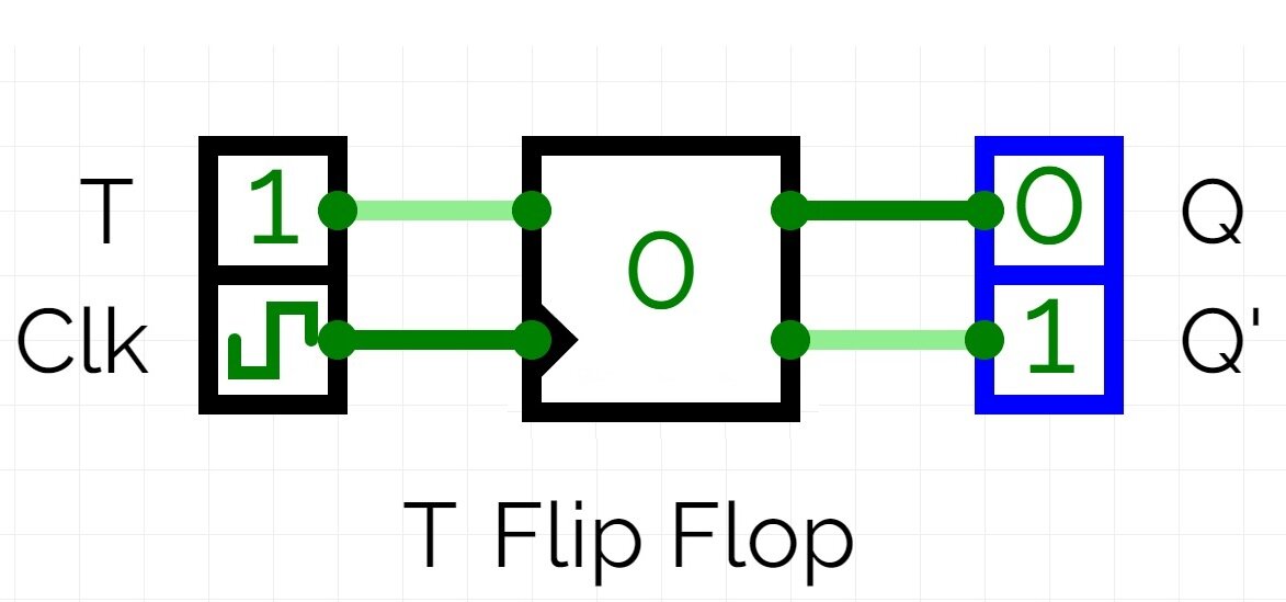
Let’s explore T flip flop truth table and working of its circuit with applications. A T flip-flop, also known as a toggle flip-flop, is a basic digital circuit element that has two stable states and can change state (toggle) based on a triggering input.
T Flip Flop Circuit Diagram:
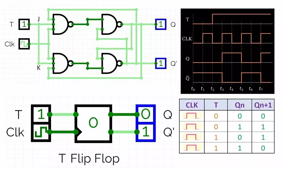
Here’s the circuit diagram for a T flip-flop using NAND gates: This T flip flop is made from JK flip flop.
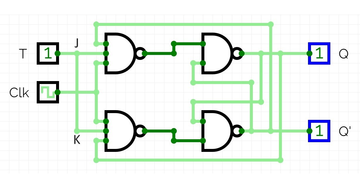
- T is the input to toggle the flip-flop state.
- Q is the output.
- Q’ is the complement of Q (NOT Q).
- T’, Q’, and Q are connected to NAND gates to create feedback loops that enable toggling behavior.
This is just one implementation of a T flip-flop. Other configurations, such as using NOR gates or D flip-flops with additional logic, are also possible.
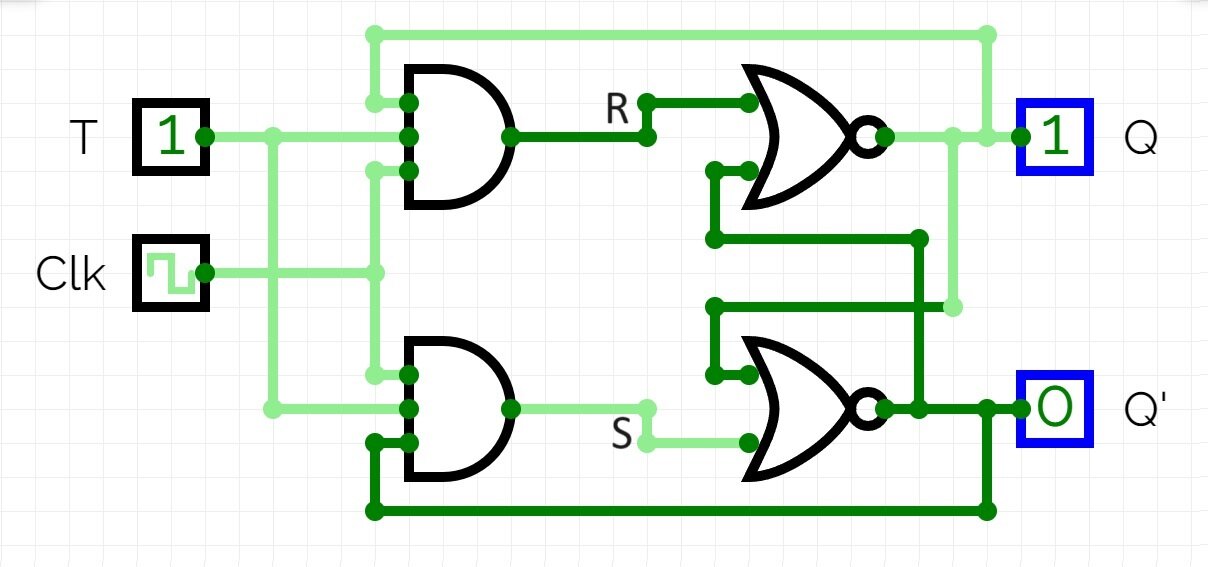
Toggle Flip Flop by SR Flip Flop:
Here is a toggle flip flop using SR flip flop. You can see that there are nor gates instead of NAND gates, so the reset section and set are exactly opposite of NAND gate based flip flop.
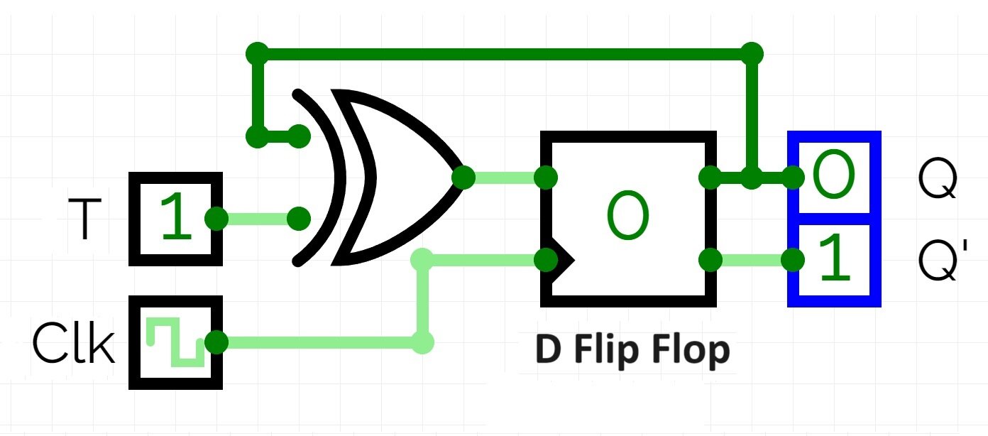
Toggle Flip Flop by using D Flip Flop:
Here we have simply added a XOR logic gate at D input of D flip flop, it combines output Q with toggle input T. This is how we convert a D flip flop into T flip flop.
Working T Flip Flop:
A T flip-flop has one input called “T” (toggle) and two outputs, typically labeled Q and Q̅ (the complement of Q). Here’s how it works:
Basic Structure: The T flip-flop is typically constructed using two cross-coupled NOR gates or NAND gates. The outputs of each gate are connected to one of the inputs of the other gate.
Initial State: Let’s say initially both Q and Q̅ are at logic level 0.
Toggle Input (T): When the T input is set to 0, the flip-flop remains in its current state, and nothing changes. However, when the T input is set to 1, the flip-flop toggles its state.
Toggle Operation: When T is set to 1, the outputs of the flip-flop swap their states. If Q is at logic level 0, it becomes 1, and if Q̅ is at logic level 1, it becomes 0. This toggle operation happens at the rising edge (or falling edge, depending on the implementation) of the clock signal if the flip-flop is clocked.
Stable State: After toggling, the flip-flop remains in this new state until the T input changes again.
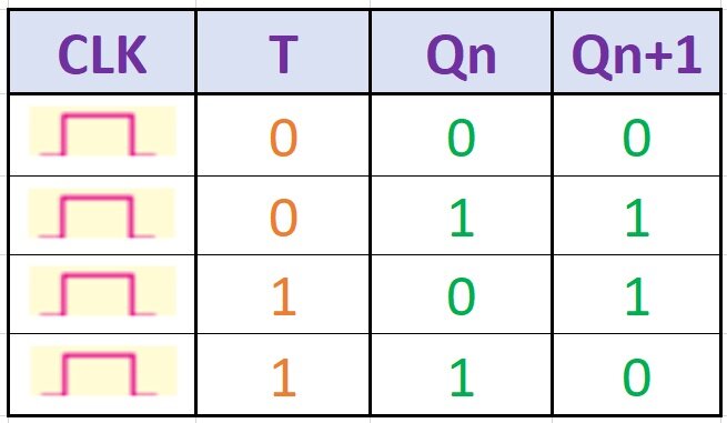
Truth Table of T Flip Flop:
The T flip-flop toggles its output state (either 0 or 1) based on the state of its input and a clock signal. Here’s the truth table for a T flip-flop:
In a T flip-flop:
- When the input T is 0, the output Q remains the same as its current state (either 0 or 1).
- When the input T is 1, the output Q toggles, switching to the opposite state from its current state.
This behavior is typically controlled by a clock signal. When the clock signal transitions, the flip-flop looks at the current state of T and toggles Q accordingly.
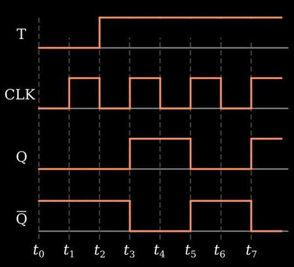
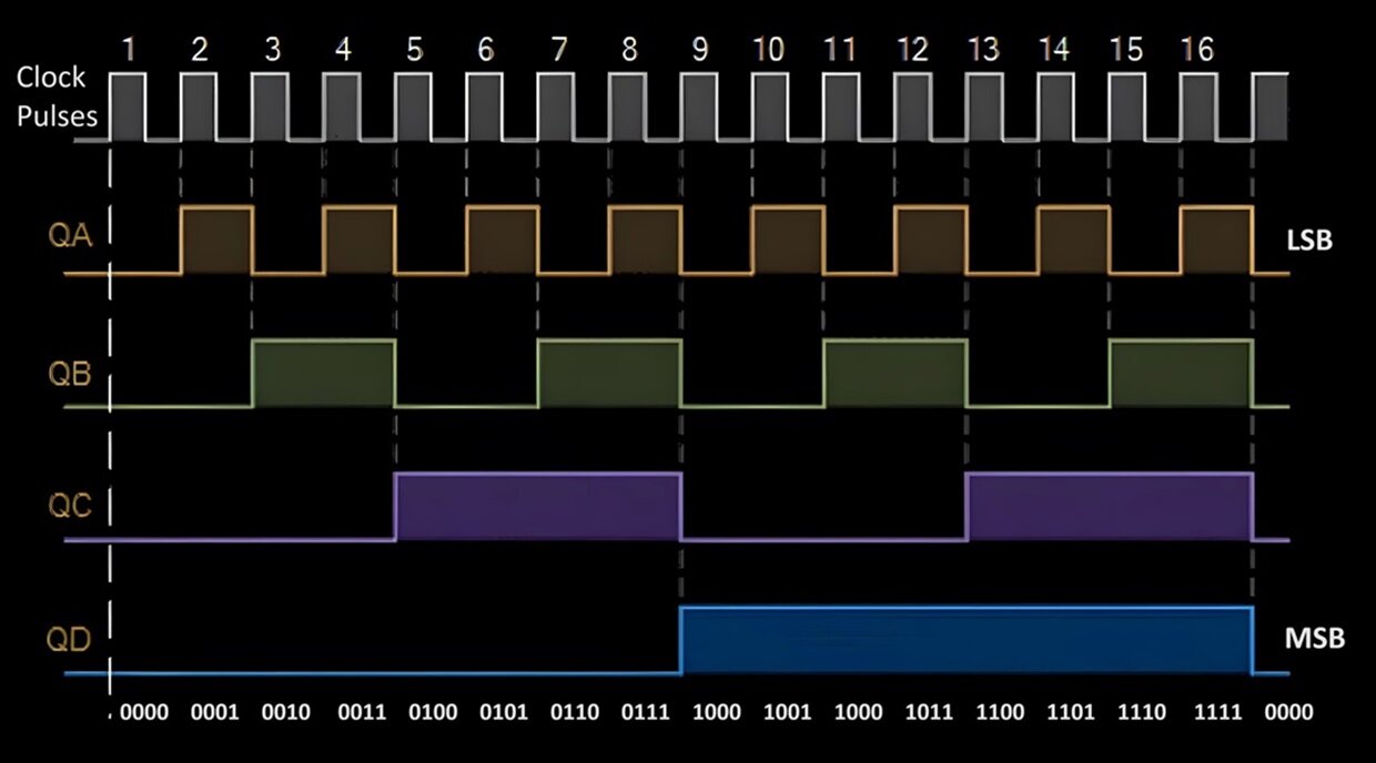
T Flip Flop Timing Diagram:
Here is the timing diagram of T flip flop,
From timing diagram, you can clearly see that there is a change in output whenever the clock pulse goes from low to high. Output Q goes to high from low and Q’ output goes to low from high state. We can state that T flip flop is positive edge triggered flip flop.
Applications of T Flip Flop:
The T flip-flop toggles its output state (either from high to low or low to high) whenever a specific condition is met. T flip-flops are commonly used in digital circuits for counters, frequency dividers, shift registers, and more, where toggling between two states is required. Here are the applications of T flip-flops:
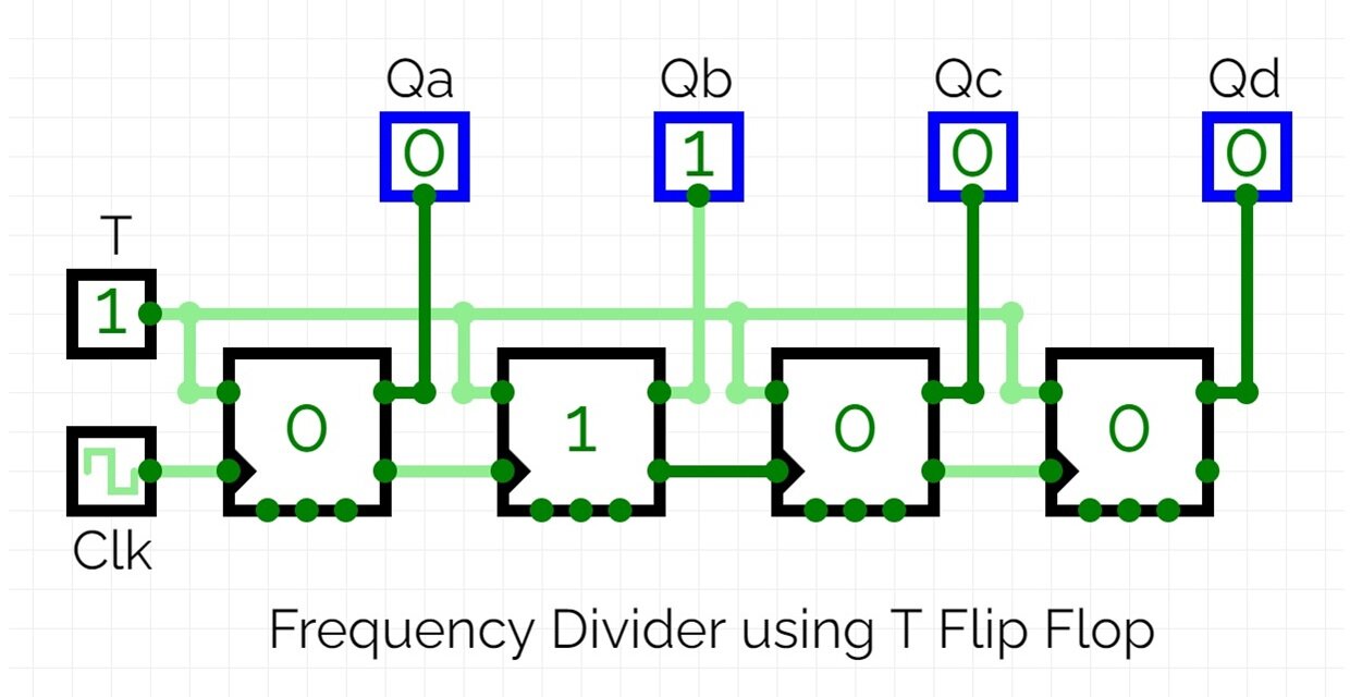
Digital Clocks:
T flip-flops are essential components in digital clock circuits. They can be used to divide the input clock frequency to generate various clock signals needed for different parts of the system.
