
Here is the circuit diagram of a peak detector circuit using opamp. A peak detector circuit is used to determine the maximum (peak) value of an input signal. It stores the maximum value of the input signal for a very long interval of time.
In many applications we need to measure the maximum value of the input signal thus we use a peak detector circuit.
If the input signal has a very low frequency, we can measure its peak value by a voltmeter. But if the signal is having a very high frequency, we can’t measure it using a voltmeter.
But if we store the peak value of the signal in a capacitor, we can easily measure it and we can use its value for our purposes.
The peak of the non-sinusoidal waveforms is measured by a peak detector circuit. A traditional ac voltmeter fails to measure the peak of such signals.
Peak detector circuit diagram:
Here is a circuit of a positive peak detector circuit.

This circuit consists of an op-amp a Diode and a capacitor. This is a very simple circuit to determine the peak value of a waveform.
Working of the circuit:
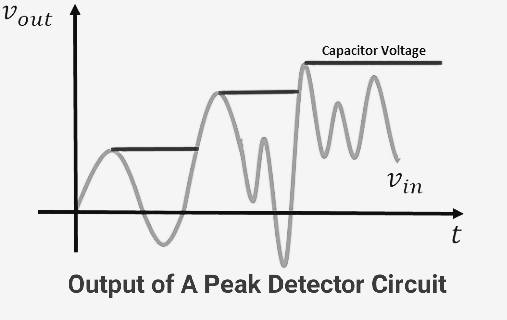
Let’s understand the working of peak detector circuit. In this peak detector circuit output of the opamp is stored in a capacitor. If the input voltage increases further, the capacitor stores it.
If we ignore the voltage drop across the diode, the capacitor charges through the diode up to the highest peak of the applied input signal. This is how the capacitor stores the highest peak of the input signal.
Let’s Consider that the capacitor initially charges to a voltage V1. Here the diode was forward biased allowing the capacitor to charge. When input signal voltage becomes lower than the V1 voltage diode gets reverse biased, and the capacitor retains the last peak value of the signal.
When the input signal voltage exceeds V1 voltage the diode again gets forward biased, and the capacitor stores the highest peak value of the signal.
This is a positive peak detector circuit. You can make a negative peak detector circuit simply just by reversing the polarities of the diode.
Modified peak detector circuit:
A modified peak detector circuit is as shown in the figure. An opamp is used to buffer the source from the capacitor.

Here two opamp are used first one is offers a high impedance and the second one acts as a buffer between load and capacitor.
Its working principle is the same as the above circuit when a higher voltage pulse arises it stores it.
The capacitor sticks to the previous higher voltage if the input voltage is small. The diode D2 restricts the output of the first op-amp from reaching negative saturation.
To reduce the effect of the offset voltage, the value of the two resistances R1 and R2 are kept equal.
Frequency compensation must be given to the first op-amp to have stability against oscillations.
Applications of Peak detector circuit:
- It is used in the mass spectrometer.
- The peak detector is used in destructive testing.
- It is used for instrumentation measurement.
- It widely finds applications in sound measuring instruments.
From the above, we can say that peak detectors circuits are used to overcome the disadvantage of the ac voltmeter. As the peak of any random waveform cannot be measured using an ac voltmeter.
Credit: falstad circuit simulator
