The Unijunction Transistor (UJT) is a three-terminal semiconductor device that is mainly used for triggering, pulse generation, relaxation oscillators, and phase control circuits. Unlike the Bipolar Junction Transistor (BJT) or Field Effect Transistor (FET), the UJT does not function as an amplifier; instead, it acts as a switching device with negative resistance characteristics.
The UJT became popular due to its simplicity, low cost, and reliability in timing and triggering applications. Despite being gradually replaced by programmable UJTs (PUTs) and other modern IC-based circuits, the UJT still holds an important place in understanding the basics of electronic switching devices.
Symbol of UJT
The symbol of unijunction transistor UJT is shown as:
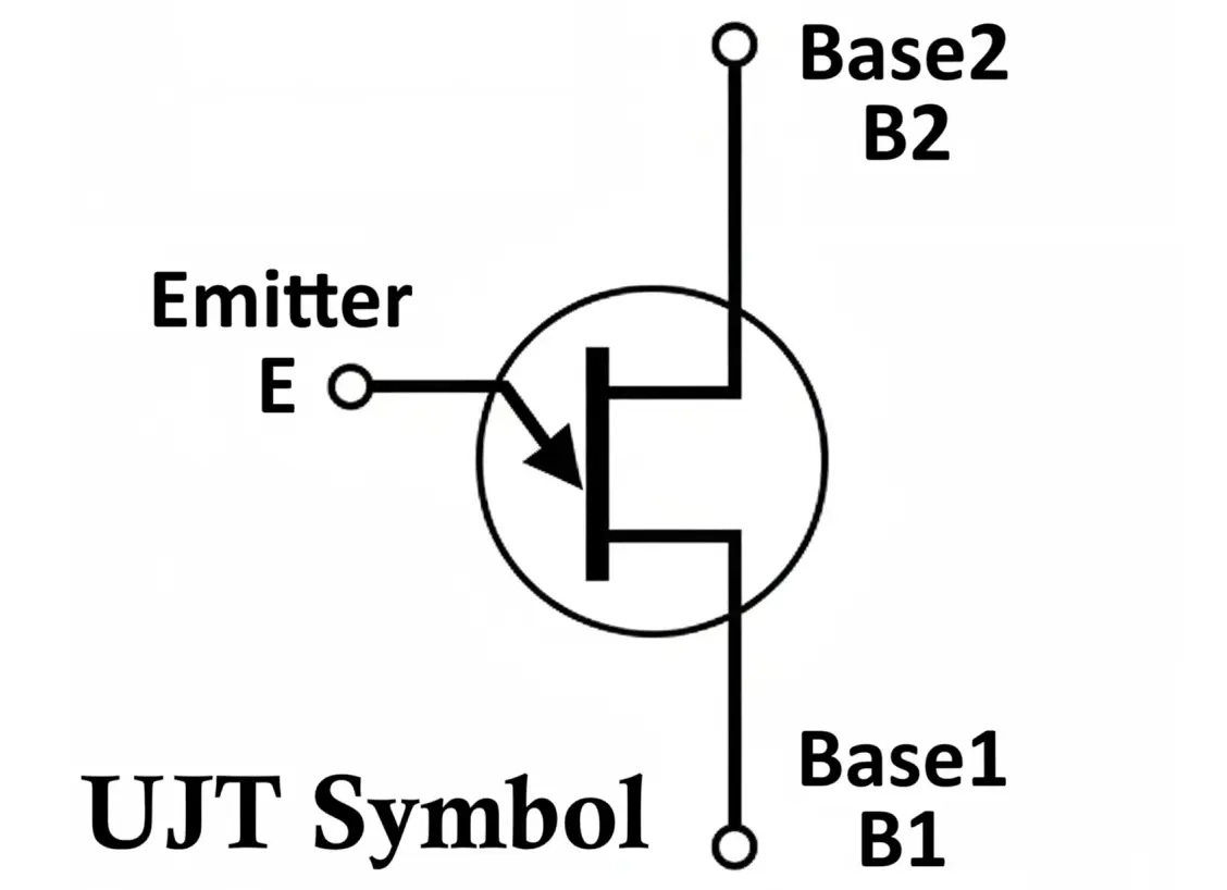
The UJT has three terminals:
- Emitter (E) – The input terminal through which current is supplied.
- Base 1 (B1) – One end of the resistive bar connected to the n-type silicon.
- Base 2 (B2) – The other end of the resistive bar.
- A diode-like emitter pointing towards a resistive bar.
- The resistive bar represents the channel between B1 and B2.
- The emitter (E) is placed diagonally and connected to the base channel through a diode.
This distinguishes it from BJTs and FETs since it has only one junction between the emitter (p-type) and the base channel (n-type).
Construction of UJT
The construction of a unijunction transistor (UJT) is relatively simple compared to BJTs or MOSFETs:
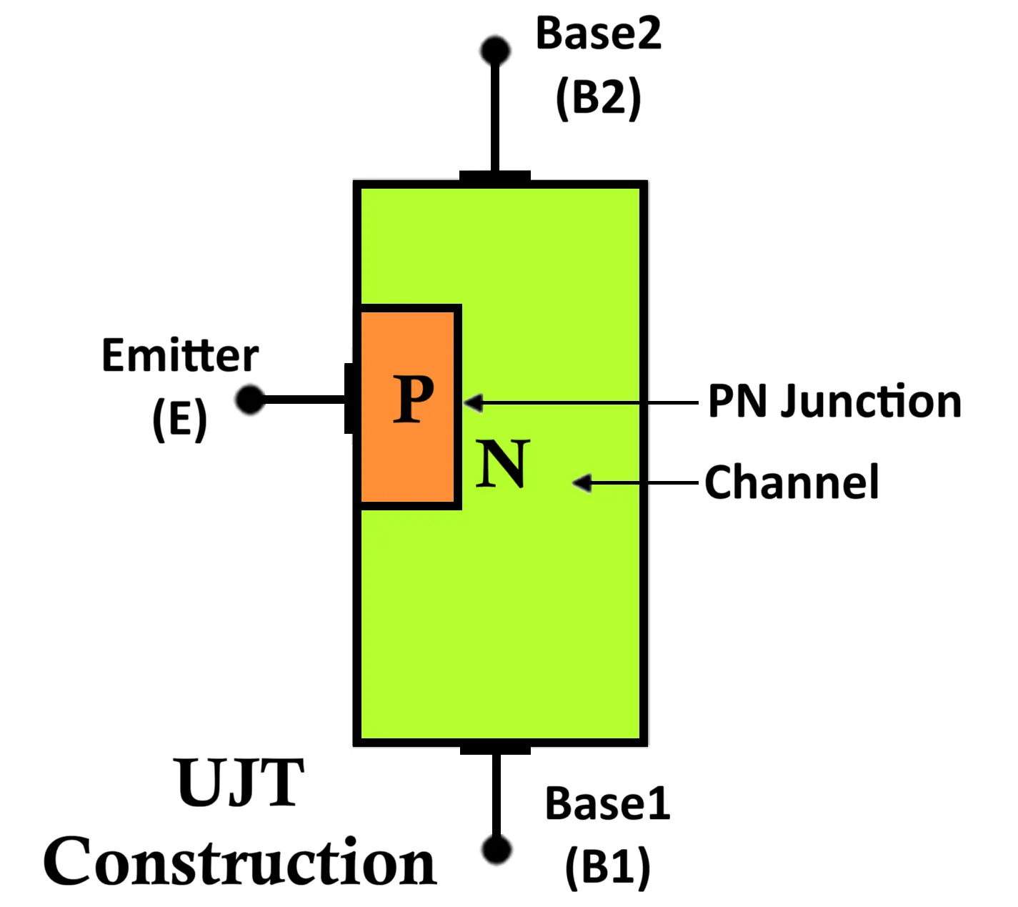
- Substrate: A bar of lightly doped n-type silicon forms the base region.
- Base Terminals (B1 and B2): Two ohmic contacts are made at the ends of this n-type bar, which form terminals B1 (lower) and B2 (upper).
- Emitter (E): A small p-type region diffuses near the B1 terminal. This makes a single p-n junction, hence it is known as Unijunction Transistor.
- Intrinsic Stand-off Ratio (η):
Since the emitter junction is asymmetrically present nearer to B1 than B2, the resistance between B1 and E (R1) and between B2 and E (R2) is different.
The intrinsic stand-off ratio (η) is defined as:
η = R1 / (R1 + R2)
where (R1) is resistance between E and B1, and (R2) is resistance between E and B2.
Typically, η ranges from 0.5 to 0.8.
Equivalent Circuit of UJT
The UJT can be represented as:
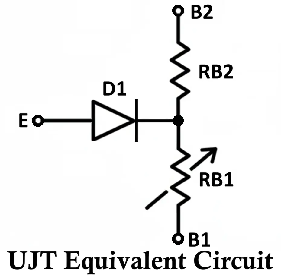
- A resistive divider formed by (R1) and (R2) between B2 and B1.
- A diode connected between the emitter (E) and the junction between R1 and R2.
This equivalent model helps in understanding how the emitter voltage influences the UJT operation.
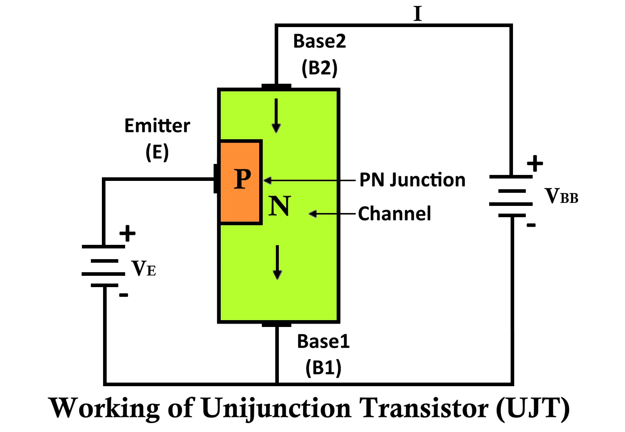
Working Principle of UJT
The operation of the UJT is based on emitter voltage (VE) applied with respect to B1 and B2.
- When emitter voltage (VE) < VP (Peak Point Voltage):
- The diode between E and the base junction remains reverse biased.
- Only a small leakage current flows.
- The UJT is in the OFF state.
- At emitter voltage = VP (Peak Point Voltage):
- The diode becomes forward biased.
- Electrons are injected into the base region.
- The resistance of R1 decreases sharply.
- Current starts flowing from emitter to B1.
- The device switches to the ON state.
The peak point voltage is given as:
VP = ηVBB + VDD
Where:
- VBB = supply voltage across B2 and B1
- VDD = forward voltage drop of the p-n junction diode (≈ 0.6–0.7 V for silicon)
- In ON state:
- Once turned ON, the UJT exhibits negative resistance characteristics, meaning as the emitter voltage increases, the emitter current increases but the emitter voltage decreases.
- This behavior is crucial for generating oscillations in relaxation oscillator circuits.
- At Valley Point Voltage (VV):
- When emitter current increases beyond a certain limit, the voltage across the emitter reaches a minimum.
- After this, the UJT behaves like a normal resistor and loses its negative resistance property.
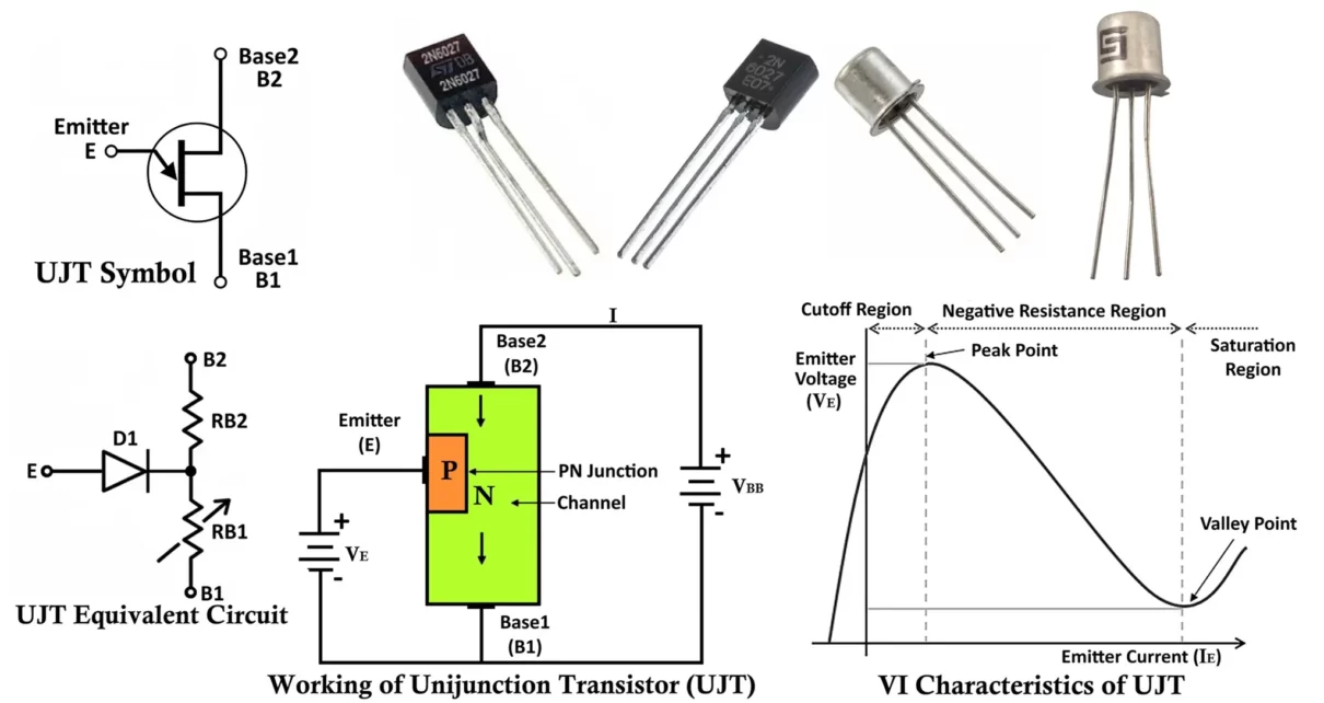
VI Characteristics of UJT
The emitter characteristics curve of UJT shows three important regions:
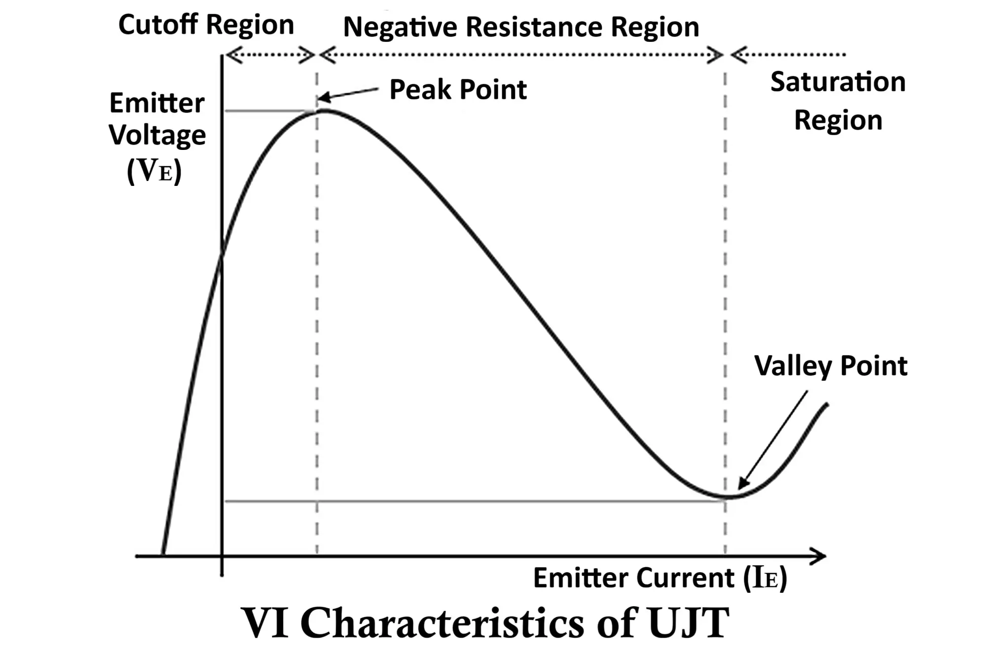
- Cutoff Region:
- For (VE < VP), only leakage current flows.
- The device remains OFF.
- Negative Resistance Region:
- When (VE>= VP), emitter current increases sharply.
- Emitter voltage decreases as current increases.
- This is the negative resistance region, widely used in oscillators and pulse circuits.
- Saturation (Valley Point) Region:
- At high emitter current, the device enters saturation.
- Beyond the Valley Point Voltage (VV), the emitter voltage starts rising again with emitter current.
This characteristic makes the UJT suitable for relaxation oscillators and triggering circuits.
UJT Relaxation Oscillator Circuit
One of the most common applications of UJT is in relaxation oscillators.
Circuit Description:
- A capacitor (C) is connected between the emitter and ground.
- A resistor (R) is connected between supply voltage (VBB) and emitter.
- B1 is grounded, and B2 is connected to the positive supply.
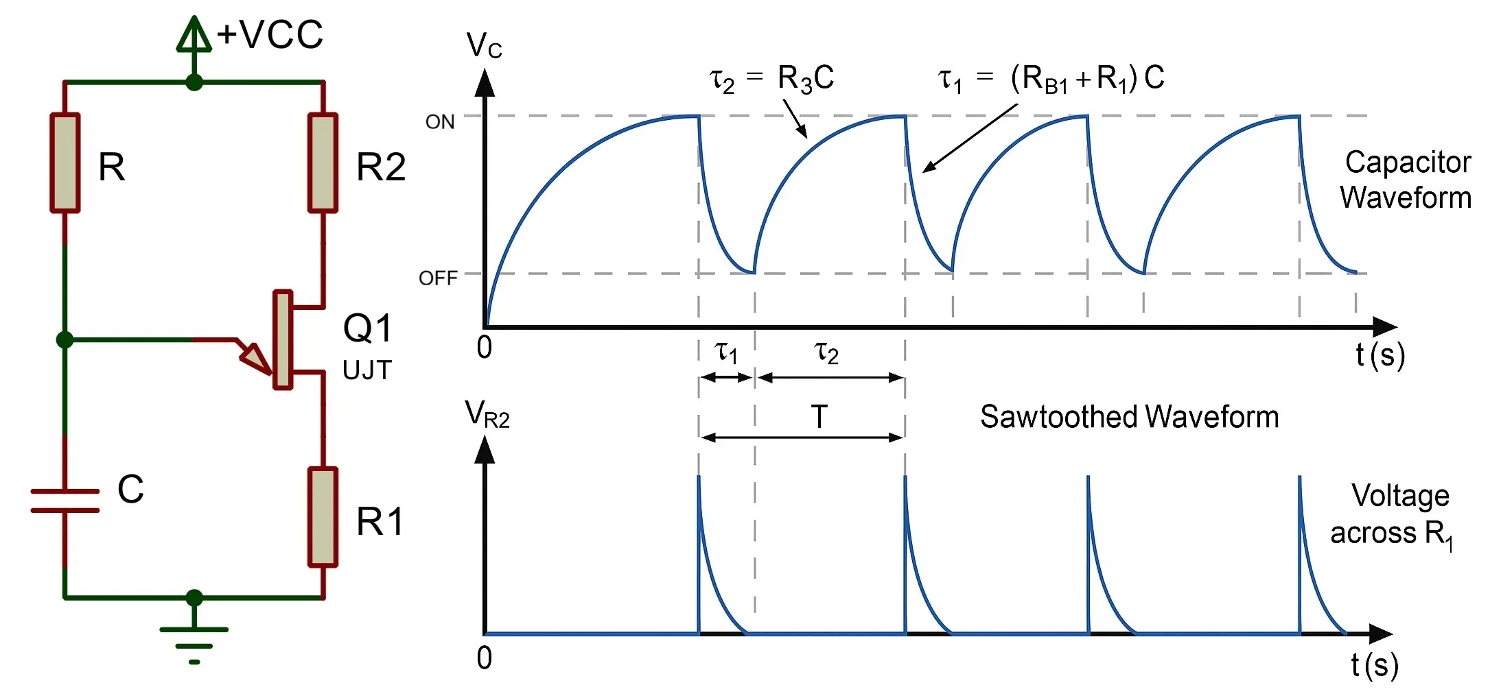
Working:
- The capacitor charges through resistor R.
- When capacitor voltage = VP, the UJT turns ON.
- The capacitor discharges rapidly through B1.
- When capacitor voltage drops below valley voltage (VV), the UJT turns OFF.
- The cycle repeats, generating a sawtooth waveform across the capacitor.
This simple oscillator is used in timing circuits and triggering SCRs in phase-control applications.
Advantages of UJT
- Low Cost & Simple Construction – Inexpensive and easy to manufacture.
- Excellent for Switching – Works well as an ON–OFF switching device.
- Low Power Consumption – Requires very little input power.
- Negative Resistance Region – Provides a stable negative resistance characteristic, useful in oscillators.
- Good Temperature Stability – Can operate reliably over a range of temperatures.
- High Pulse Current Capacity – Can handle relatively large pulse currents.
- Reliable Triggering – Provides consistent triggering signals for SCRs, TRIACs, etc.
Disadvantages of UJT
- Low Current & Voltage Handling – Cannot handle high power; limited to small-signal applications.
- Low Switching Speed – Not suitable for high-frequency operations.
- Fixed Intrinsic Stand-Off Ratio (η) – Limits design flexibility.
- Replaced by Modern Devices – BJTs, MOSFETs, and programmable unijunction transistors (PUTs) are often preferred.
- Not Linear – Can’t be used for amplification like BJTs or FETs.
Applications of UJT
- Relaxation Oscillators – For generating sawtooth and timing pulses.
- Triggering Circuits – To trigger SCRs, TRIACs, and other thyristors in power control.
- Phase Control Circuits – Used in light dimmers, motor speed controllers, and heater controls.
- Timing Circuits – Provides time delays in control systems.
- Waveform Generators – For pulse, sawtooth, and staircase waveform generation.
- Voltage Regulators – As part of regulating and sensing circuits.
- Alarm & Sensing Circuits – Fire alarms, temperature sensors, etc.
- Pulse Generation – Used in digital logic and signal processing.
Conclusion
The Unijunction Transistor (UJT) is a unique semiconductor device that works on the principle of a single p–n junction. With its negative resistance region, the UJT ideally serves relaxation oscillators, pulse generation, and triggering applications. Modern electronic circuits rarely use UJTs because IC-based solutions and programmable UJTs offer better alternatives. Still, the UJT plays an important role in learning the fundamentals of transistor switching and oscillator design. 2N2646, 2N1671 and 2N6027 are some of the popular UJTs.
By studying its symbol, construction, circuit, operation, VI characteristics, advantages, disadvantages, and applications, one gains a complete and practical understanding of how the UJT functions and where it proves most effective.
Phototransistor – Construction, Working, Types and Applications
Types of Transistors: Classification (BJT, JFET, MOSFET & IGBT)
JFET Junction Field Effect Transistors Working and Applications
IGBT Full Form, Symbol, Construction, Working and Applications
