Skip to content

Hackatronic

Hacks of Electronics

  • Home
  • Electronics Calculators
  • Electronic components
    • Active components
    • Passive components
  • PCB ASSEMBLY
  • Types of Diode
    • Zener Diode
    • Working of Diode
    • Shockley Diode
  • Electronics tutorial
    • Raspberry Pi
    • Counter Circuits
    • Flip Flops
  • 555 Timer
  • Electronics project
    • ESP32
    • Arduino
    • BC 547 Projects
    • Power supplies
    • Protection Circuits
  • Operational Amplifiers
    • OP-AMP tutorial
    • 741 Op Amp IC
    • OP Amp Basics Concepts
    • Opamp based project
  • About Hackatronic
  • Contact Us
  • Privacy policy

Tag: lm317 adjustable voltage regulator circuit diagram

LM317 adjustable power supply circuit
Electronics tutorial Power supplies

LM317 adjustable voltage regulator circuit

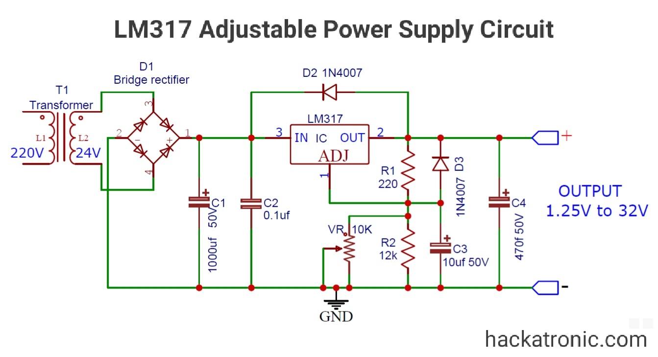
LM317 is an adjustable voltage regulator IC. In this project, we will be making a 1.25V to 37V LM317 adjustable voltage regulator circuit. This IC can provide an output current up to 1Amp. It’s a three-terminal positive voltage regulator IC. This voltage regulator requires only two external resistors to set the supply voltage. It has […]

Posted on 12/12/202021/12/2024 Author Abhishek Singh Comments(6)

Topics To Explore

  • Arduino (17)
  • Circuit Designing (16)
  • Communication technologies (8)
    • 5G technology (1)
  • Computer Science (16)
    • Artificial Intelligence AI (3)
    • Information Security (2)
  • Electronics tutorial (218)
    • Arduino based projects (24)
      • ESP32 (13)
    • Boolean Algebra (10)
    • Counter Circuits (20)
    • Counter ICs (6)
    • Digital Electronics (16)
      • Microprocessors (1)
    • Electronic components (59)
      • Active components (36)
        • Transistors (19)
          • BJT (2)
          • IGBT (3)
          • JFET (2)
          • MOSFET (7)
      • Passive components (10)
    • Electronic devices (39)
      • FPGA (4)
      • Motor Drives (2)
    • Electronics project (50)
      • Bc 547 transistor projects (7)
    • Filter Circuits (1)
    • Flip Flops (15)
    • Integrated circuits (ICs) (34)
      • 555 timer IC (9)
    • Logic Gates (20)
      • NAND Gate (3)
      • NOR Gate (5)
    • Microcontrollers (6)
    • Oscillators (5)
    • Power supplies (28)
      • DC Power Supply (18)
        • DC-DC Converters (4)
      • Inverters (7)
      • SMPS (2)
    • Protection Circuits (9)
    • Raspberry Pi (5)
      • Raspberry Pi IOT Projects (3)
    • Types of Diode (13)
      • Shockley Diode (1)
      • Working of Diode (10)
      • Zener Diode (1)
  • ESP8266 (1)
  • Gadgets (7)
  • Internet of Things (17)
  • IOT (18)
  • Manufacturing (10)
  • OP-AMP tutorial (28)
    • Opamp based project (12)
      • Amplifier Projects (5)
    • Operational amplifier basics (10)
  • PCB Designing (15)
    • DFM Tool (3)
    • high frequency PCB design (4)
  • PCB Manufacturing (18)
    • PCB Assembly (4)
  • Sensors (12)
  • Solar Energy (3)
  • Tech one (6)
    • Google (1)
  • Three Phase AC (1)
  • Thyristor Family (3)

datasheet

Datasheet Search

Recent comments

  • Abhishek Singh on SG3525 PWM Inverter Circuit Diagram and it’s Working
  • Enwongho on SG3525 PWM Inverter Circuit Diagram and it’s Working
  • Abhishek Singh on 12V 10A SMPS: Switched Mode Power Supply Circuit – IC DM0565
  • NgPark on 12V 10A SMPS: Switched Mode Power Supply Circuit – IC DM0565
  • Abhishek Singh on 12V 10A SMPS: Switched Mode Power Supply Circuit – IC DM0565
  • Arduino
  • ESP32
  • Raspberry Pi
  • Electronic components
  • OP-AMP tutorial
  • Counter Circuits
  • Flip Flops
  • Power supplies
  • Types of Diode
  • YouTube
  • Pinterest
  • Facebook
  • Instagram
  • LinkedIn
  • X
Join WhatsApp Channel
  • PCB ASSEMBLY
  • Electronics tutorial
  • Electronics project
  • Integrated circuits (ICs)
  • Resistor color code calculator
  • About Hackatronic
  • Contact Us
  • Privacy policy
  • Disclaimer
2025 hackatronic.com