
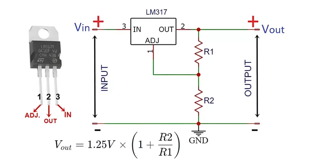
LM317 is an adjustable voltage regulator IC. In this project, we will be making a 1.25V to 37V LM317 adjustable voltage regulator circuit. This IC can provide an output current up to 1Amp. It’s a three-terminal positive voltage regulator IC.
This voltage regulator requires only two external resistors to set the supply voltage. It has a line regulation of around 0.01% and load regulation of about 0.1%. It also has a current limiter and thermal protection. You can use this LM317 calculator to calculate output voltage or resistance of voltage divider.
Features of LM317:
Here are some important features of LM317 positive voltage regulator:
- Adjustable output voltage range from 1.25 V to 37 V
- Output current more than 1.5 A
- Internal short-circuit current limiter
- Thermal overload protection
- Output safe-area compensation
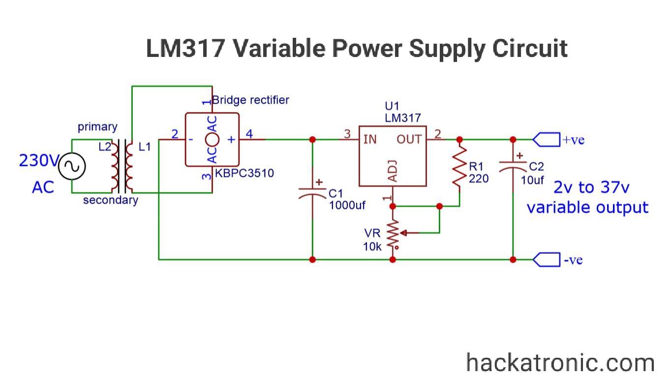
LM317 voltage regulator Circuit Diagram:

Circuit explanation:
This circuit is consisting of the following components.
Transformers:
It steps down 220V AC to 24V AC having lesser amplitude.
Rectifier:
It converts sinusoidal AC input to a unidirectional DC pulsating voltage which is not stable and contains ripples.
Capacitive filter:
A capacitive filter of 1000uf filters out most of the ripples from the output of the bridge rectifier.
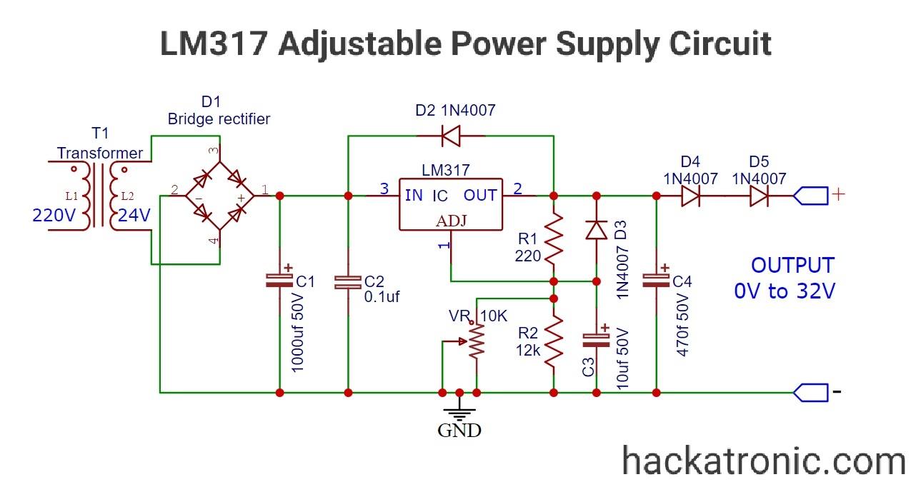
LM317 positive voltage regulator:
This three-terminal IC can regulate output voltage from 1.25V to 37V. The output voltage depends on the voltage divider circuit formed by the 220ohm resistor and a 12kohm resistor. A 10kohm potentiometer is used to vary the voltage at adjust terminal of IC. Pin number 3 is the input terminal and 2 is the output terminal, while the first pin is the adjust pin.
Protection circuit:
Two 1N4007 Diodes are connected to the IC in the reverse direction. If a wrong high voltage supply is given to the IC, it may get damaged. These two diodes protect the IC from damage by providing an alternate path to the high current.
Finally, a 470uf capacitor is used in parallel to make the output more stable.
LM317 Tutorial:
must watch this video.
Working of LM317 adjustable voltage regulator circuit:
LM317 is a linear voltage regulator. The step-down transformer gives RMS 24 volt, 2A output. This output is not stable so a 1000uf capacitor is used to make it smooth and stable by removing the ripples.
This voltage is then given to the input pin of the LM317 variable voltage regulator IC. This IC produces an output voltage depending on the adjust terminal.
The voltage across the feedback resistor R1 is about 1.25V constant. Due to this reference voltage, a constant current of 100uA flows through the adjust terminal. Due to the 1.25V reference voltage, a current flows through resistor R2.
The output voltage is proportional to the voltage drop across resistor R1 and R2.
Vout = Vref x {1+ (Rp/R1)
Here, Vref = 1.25V
Rp = VR || R2, 10k pot and R2 are in parallel
When we set the potentiometer to the lowest zero resistance the output voltage becomes 1.25V. As Rp = 0ohm from the above formula,
Vout = 1.25 x {1+(0/220)}
= 1.25V
When we put the potentiometer to the highest resistance the parallel resistance becomes
Rp = 5.4545k ohms
So the output voltage due to this resistance becomes,
Vout = 1.25 x {1+(5454.5/220)}
= 32.2V
Bay choosing the correct value of resistance you can set the output voltage.
How to make it work from 0V?
If you want to control the output from 0 volts you should connect two Diodes in series to the output of the circuit. As the voltage drop across the 1N4007 diode is about 0.7V total you will get a drop of about 1.3 to 1.4 volt. By using this technique you can control the output from 0 volts, but the current will get reduces.
Also if you want to adjust a fine voltage connect a 1k potentiometer in series with the 10k potentiometer.
Use a Heatsink:
You must use a heatsink as the LM317 IC is a linear voltage regulator. Around 2.5 volt is the voltage drop across this IC. This voltage drop causes a lot of heat. This heating may cross the thermal threshold of IC which may damage the IC. So, to protect the IC you must use a good heat sink and cooling solution.
So this is a variable voltage power supply circuit capable of supplying more than 32V at 1.5A of output current.
Applications of LM317 adjustable voltage regulator circuit:
- Power supply of PC’s
- Power Bank
- Lab power supply module
- Battery charger circuit
- Motor speed controller
- Signal or waveform generator
- Electronics appliances and home utilities

Seems amazing, I’m going to build a 22 v charger for a small vacuum cleaner using this circit.
What is the transformer rating for the 0-37V circuit?
Use 24V transformer
small detail on the first graph: the ouput can’t be bigger than 24v.
Input maximum ampr…….???
Output current is almost equal to input current