We see numbers displayed on many electronic devices around us, like digital clocks, calculators, microwave ovens, and scoreboards. But have you ever wondered how these numbers appear on the screen? One of the most common ways to show numbers in electronic devices is by using a Seven Segment Display. It is a simple electronic component that lights up small bars or “segments” to form numbers, making it easy for us to read information quickly. Understanding how a Seven Segment Display works helps us learn the basics of electronics and how devices show data.
What is a Seven Segment Display?
A Seven Segment Display (SSD) is an electronic display device used to display decimal numerals and some alphabetic characters. It is widely used in digital clocks, electronic meters, calculators, and other devices that display numerical information. The display consists of seven individual segments (LEDs or LCDs) arranged in a figure “8” pattern. By illuminating selected segments, we can represent numbers from 0 to 9 and some letters.
Construction of Seven Segment Display
A typical Seven Segment Display consists of 7 light-emitting diodes (LEDs) arranged in a specific pattern and numbered from ‘a’ to ‘g’. Each segment is an individual LED that can be turned ON or OFF by applying appropriate voltage and current.
Seven Segment Display Pinout Diagram:
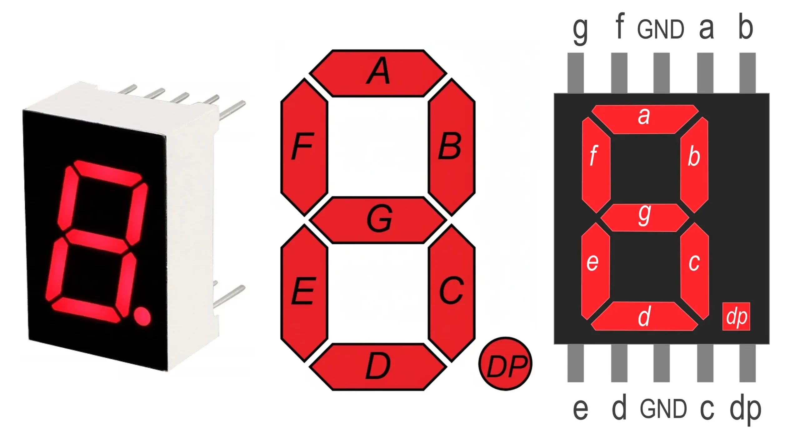
- a, b, c, d, e, f, g are the segments.
- An additional LED is often used for the decimal point (DP).
- There are total 10 pins: 7 pins are for segment LEDs (a to g), 1 pin is for the decimal point (DP), and 2 ground (common cathode) pins.
Materials:
- Segments are made of LEDs in an LED-based SSD.
- A plastic or glass casing protects the assembly.
- Each segment has an individual lead (or shared depending on type).
Working of Seven Segment Display
When a suitable voltage is applied across the correct pins of the display, current flows through the specific LEDs (segments), and they emit light. By controlling which segments are ON and which are OFF, various digits (0-9) and some alphabets (A-F) can be displayed.
For example:
- To display the digit “8”, all seven segments (a, b, c, d, e, f, g) are turned ON.
- To display the digit “1”, only segments b and c are turned ON.
Control can be achieved using microcontrollers, counters, decoders, or manual switches by providing HIGH or LOW logic levels to the pins.
Types of Seven Segment Display
There are two primary types of Seven Segment Displays based on how their LEDs are connected internally:
- Common Cathode (CC) Seven Segment Display
- Common Anode (CA) Seven Segment Display
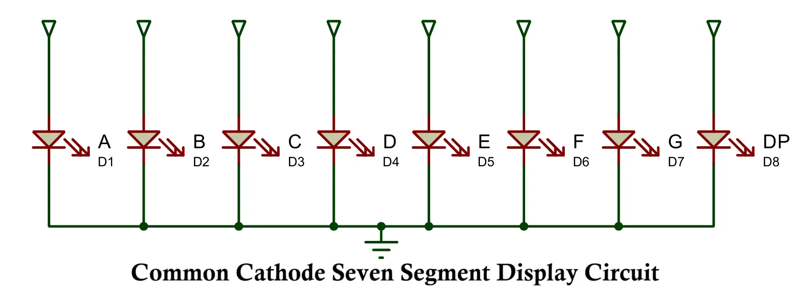
Common Cathode (CC) Seven Segment Display
In a Common Cathode Seven Segment Display, all the cathode (negative) terminals of the LEDs are connected together and usually grounded. To light up a segment, a logic HIGH voltage (usually +5V) is applied to the corresponding anode pin.
Working Principle:
- Cathode pins are common and connected to ground.
- Individual segments light up when their anode pins are supplied with logic HIGH.
Example:
To display “5”:
- Apply HIGH to segments a, f, g, c, and d.
- Other segments remain OFF.
Advantages:
- Easy to interface with microcontrollers (common logic HIGH control).
- Suitable for direct logic applications.
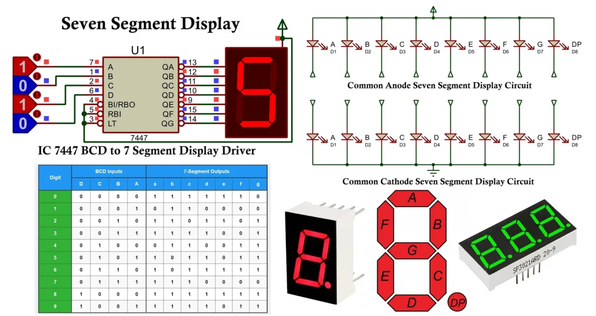
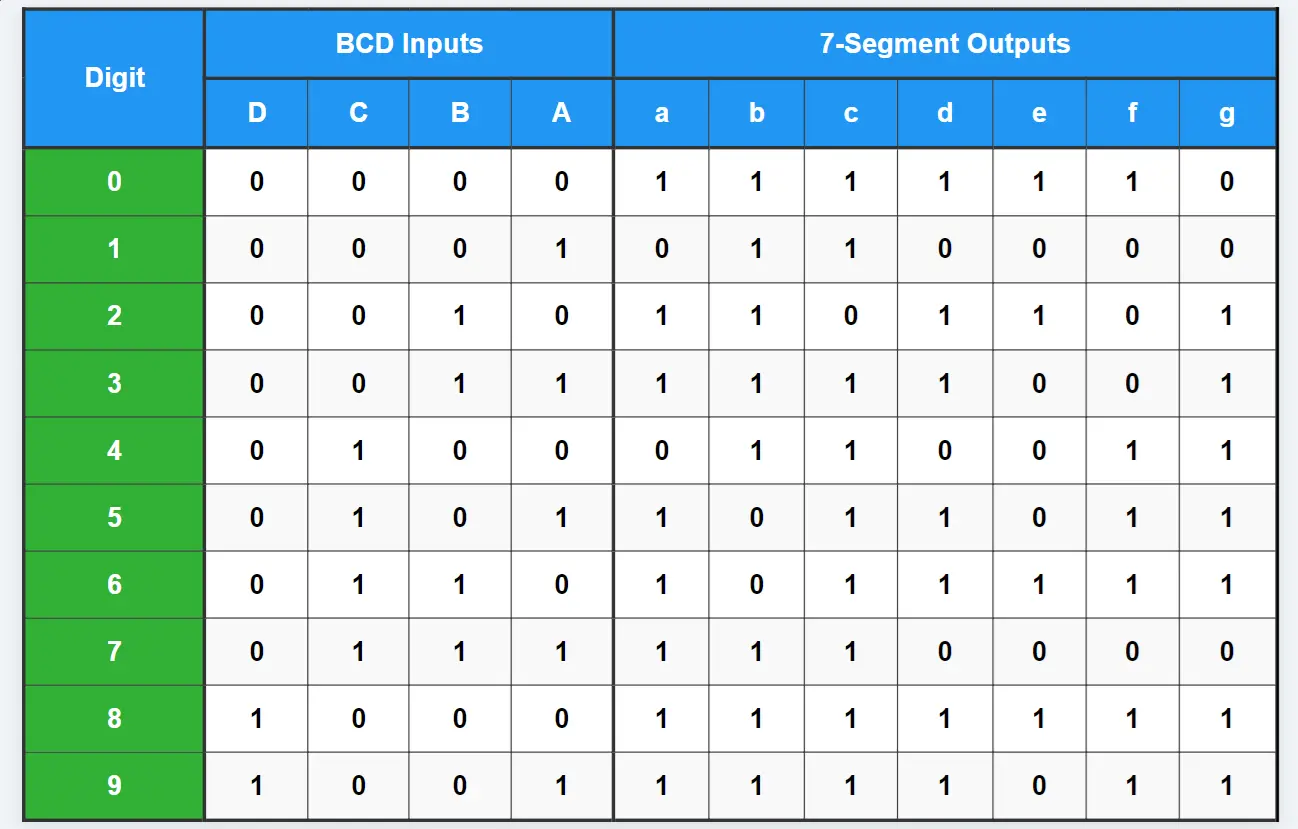
Here is the truth table of common cathode seven segment display. In case of common anode all the values change from 1 to 0 and everything remains the same.
Common Anode (CA) Seven Segment Display
In a Common Anode Seven Segment Display, all the anode (positive) terminals of the LEDs are connected together and connected to a positive voltage supply (usually +5V). To light up a segment, a logic LOW (0V) is applied to the respective cathode pin.
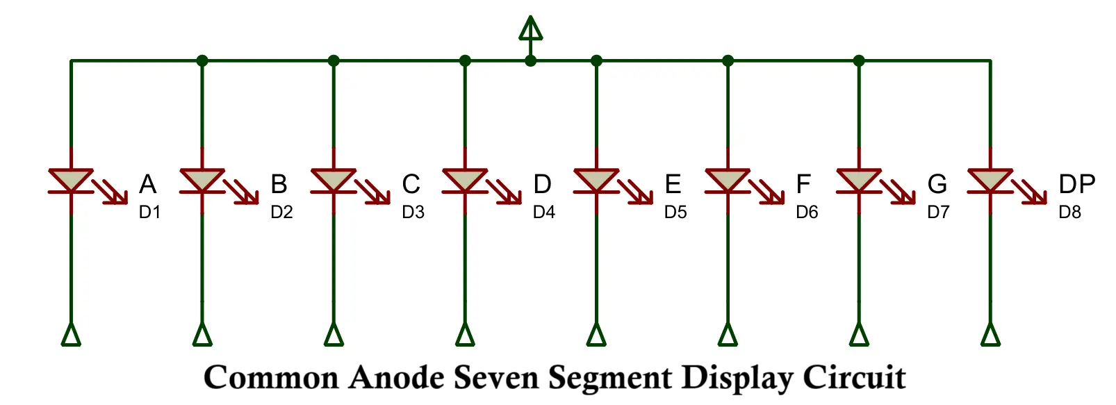
Working Principle:
- Anode pins are common and connected to Vcc (+5V).
- Individual segments light up when their cathode pins are pulled LOW.
Example:
To display “2”:
- Apply LOW to segments a, b, g, e, and d.
- Other segments remain OFF.
Advantages:
- Easier in circuits where sinking current is preferable.
- Compatible with open-collector output circuits.
Protecting LEDs from High Current
LEDs used in Seven Segment Displays are sensitive devices and can be damaged by high currents. Therefore, current-limiting resistors are always connected in series with each segment to protect the LEDs from overcurrent.
Calculation of Resistor Value:
Using Ohm’s Law:
R = (Vsupply − VLED) / ILED
Where:
- Vsupply = Supply voltage (usually 5V).
- VLED = Forward voltage of the LED (typically 2V for red LEDs).
- ILED = Desired current through the LED (typically 20mA).
Example:
Vsupply = 5V, VLED = 2V, ILED = 20mA = 0.02A
So: R = (5V − 2V) / 0.02A = 150Ω
A resistor of 150Ω is connected in series with each segment.
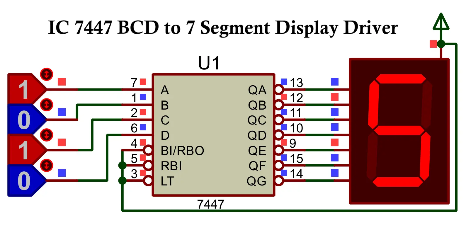
IC 7447 – BCD to 7 Segment Display Driver IC
The IC 7447 is a popular BCD (Binary-Coded Decimal) to 7-Segment Display Driver IC that converts a 4-bit BCD input (0000 to 1001) into signals for driving a common-anode 7-segment display.
Key Features:
- Converts BCD input (0000 to 1001) into appropriate signals for a 7-segment display (digits 0–9).
- Designed for Common-Anode 7-Segment Displays.
- Provides active LOW outputs for driving segments.
- Includes control pins:
- Blanking Input (BI) – Used to turn off the display (all segments OFF).
- Lamp Test (LT) – Lights up all segments for testing purposes.
- Ripple Blanking Input (RBI) – Controls ripple blanking between multiple ICs in cascaded setups.
- Operates at standard +5V supply voltage.
Pin Configuration: 1-a, 2-b, 3-c, 4-d, 5-e, 6-f, 7-g, 8-GND, 9-D (BCD MSB), 10-C, 11-B, 12-A (BCD LSB), 13-BI (Blanking Input), 14-LT (Lamp Test), 15-RBI (Ripple Blanking Input), 16-Vcc.
Working Principle:
- User provides a 4-bit BCD input (A, B, C, D) through pins 12 to 9.
- The IC decodes the BCD and provides active LOW outputs to segments a–g of the 7-segment display.
- Control Pins:
- BI (Blanking Input):
- BI = LOW (0): Display is blanked (all segments OFF).
- BI = HIGH (1): Normal operation.
- LT (Lamp Test):
- LT = LOW (0): All segments light up for testing.
- LT = HIGH (1): Normal operation.
- RBI (Ripple Blanking Input):
- Used for cascading multiple 7447 ICs to suppress leading zeros in multi-digit displays.
- BI (Blanking Input):
Example:
- BCD Input = “0001” (Decimal 1):
Segments b and c are activated → Displays “1”. - BCD Input = “1010” (Decimal 5):
Segments a, c, d, f, g are activated → Displays “5”.
Advantages of IC 7447:
- Simple solution for interfacing BCD logic to 7-segment displays.
- Reduces the number of external components needed.
- Built-in test and blanking controls ease debugging and advanced display designs (multi-digit).
- Reliable and standardized for common digital display applications.
Applications of Seven Segment Display
Here are the key applications of Seven Segment Displays (SSD):
- Digital Clocks:
Displays hours, minutes, and seconds in digital format.
Easy to read and widely used in wall clocks, alarm clocks, etc. - Electronic Meters:
Used in voltmeters, ammeters, frequency counters, and other measurement devices.
Displays numeric readings of electrical quantities. - Calculators:
Displays numbers and simple symbols in hand-held or desktop calculators.
Provides user-friendly digital readout. - Digital Counters:
Used in devices that count events, pulses, or time intervals.
Example: People counters, production counters in factories, etc. - Digital Thermometers:
Displays temperature readings in numeric form.
Often used in household and industrial temperature measurement devices. - Microwave & Oven Displays:
Shows time settings, temperature, and cooking modes.
Simple and reliable numeric display for user interaction. - Scoreboards:
Used in sports scoreboards to display scores, timer, and game information.
Provides bright, large numeric display. - Weighing Machines:
Displays weight measurements in kilograms or pounds.
Clear numeric display for quick readings. - Digital Panel Meters:
Displays analog signals (converted to digital) for industrial process monitoring.
Example: Pressure, flow, and voltage display panels. - Embedded Systems:
Provides visual numeric output in microcontroller projects.
Widely used in educational and hobbyist projects.
Conclusion
The Seven Segment Display is a simple yet powerful component that finds vast applications in digital electronics. Understanding the types (Common Cathode vs. Common Anode), the working principles, the role of current-limiting resistors, and the advantages of using ICs like the 7447 helps in designing efficient and reliable display systems. Whether you’re building a simple counter or a complex embedded system, the Seven Segment Display remains a fundamental building block for numerical output.
