In modern electronics, signal isolation between different parts of a circuit is crucial for protection, noise reduction, and system stability. Optocouplers, also known as optoisolators, play a vital role in achieving this electrical isolation while allowing signal transmission. This article provides a thorough exploration of optocouplers (Optoisolator / Photocoupler), including their construction, working principles, advantages, disadvantages, and practical applications.
What is an Optocoupler (Optoisolator / Photocoupler)?
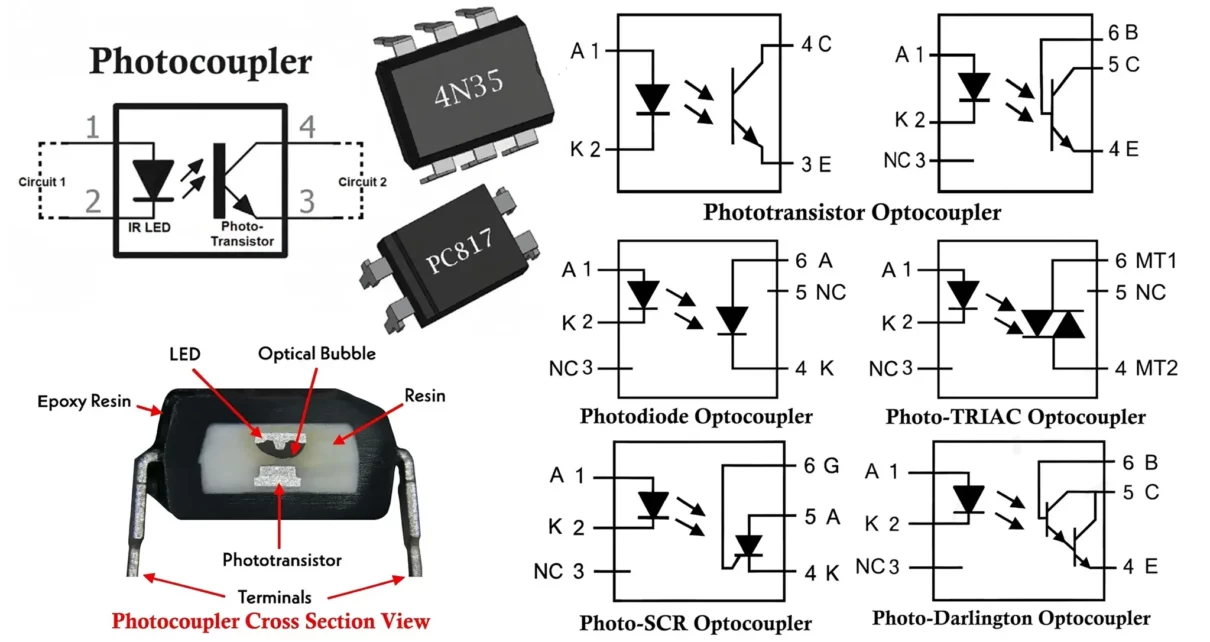
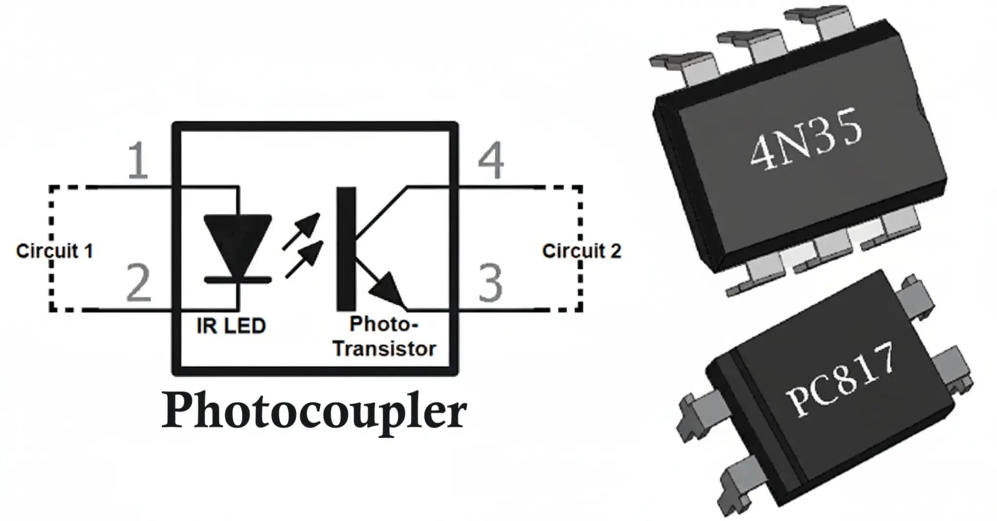
An Optocoupler (Optoisolator / Photocoupler) is an electronic component that transfers electrical signals between two isolated circuits by using light. It allows signals to pass while maintaining electrical isolation between the input and output, preventing high voltages or noise from affecting the low-voltage control side.
Key Idea: The input circuit activates a light-emitting device, and the output circuit responds to the light using a photodetector, ensuring no direct electrical connection.
Optocoupler (Optoisolator / Photocoupler) Construction
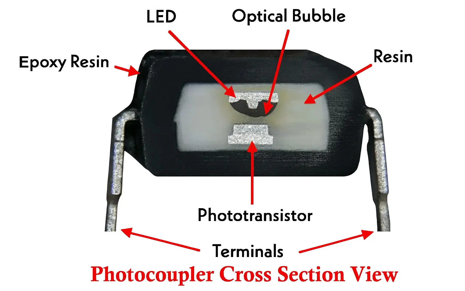
An optocoupler (also known as an optoisolator or Photocoupler) consists of two core components housed within a single sealed package, enabling electrical signal transmission with galvanic isolation between circuits.
1. Light Emitter (Input Side)
The input side includes an infrared LED, typically made from gallium arsenide (GaAs), operating in the 850–950 nm wavelength range. Key characteristics of the LED are:
- Forward Voltage: Approximately 1.2–1.5 V at rated current
- Input Current Range: Generally, 5–100 mA, depending on application needs
2. Photodetector (Output Side)
The photodetector converts the incoming light back into an electrical signal. Various types are used depending on application requirements:
- Phototransistor (most common): NPN or PNP bipolar transistor
- Photodarlington: Provides higher current gain using a two-transistor configuration
- Photodiode: Offers fast response and linearity, ideal for high-speed applications
- Photo-SCR (Silicon Controlled Rectifier): Used in AC power control
- Photo-TRIAC: Enables bidirectional AC switching
- Photovoltaic Cell: For generating electrical output from light
Isolation Barrier
Between the LED and photodetector lies a transparent, electrically insulating barrier, critical for maintaining electrical isolation:
- Materials: Glass, air, or transparent epoxy resin
- Isolation Voltage: Typically between 1,500 V and 10,000 V RMS
- Insulation Resistance: Exceeds 10¹² ohms
Package Configuration
Standard packaging formats include:
- 4-pin DIP (Dual In-line Package) – Common
- 6-pin DIP (Dual In-line Package) – Most common
- 8-pin DIP – Used for high-speed or dual-channel designs
- SMD (Surface Mount Device) – Modern compact designs for automated assembly
Working of Optocoupler (Optoisolator / Photocoupler)
An optocoupler (also known as an optoisolator or Photocoupler) operates via a simple yet effective electro-optical-electrical conversion process:
1. Electrical-to-Optical Conversion
An input electrical signal drives current through the LED, causing it to emit infrared light. The light intensity is directly proportional to the input current.
2. Optical Coupling
The emitted light crosses the isolation barrier and illuminates the photodetector, ensuring full electrical isolation between input and output circuits.
3. Optical-to-Electrical Conversion
The photodetector responds to the light by generating an electrical signal. In the case of a phototransistor, the light serves as a base current, modulating collector-emitter conduction.
Operating Modes of Phototransistor
The phototransistor can function in two different modes:
Saturation Mode (Switching)
In saturation mode, the optocoupler operates as a switch with two distinct states: ON and OFF. In the ON state, it conducts maximum current, while in the OFF state, it completely blocks current flow. This mode is typically used to control high-power circuits via a microcontroller or digital logic circuit by switching them ON or OFF.
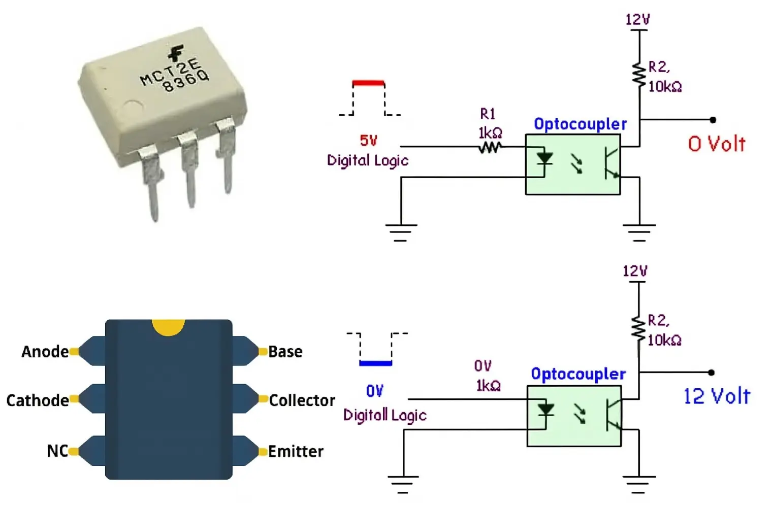
Optocoupler with a Phototransistor Output:
- When the LED is ON, the phototransistor conducts, allowing current to flow in the output circuit, making output LOW.
- When the LED is OFF, the phototransistor remains non-conductive, making output HIGH.
Linear (Active) Mode (Amplification)
In linear or active mode, the output current of the phototransistor varies proportionally with the intensity of the incoming light, which in turn depends on the input current. This mode is commonly used for amplification purposes, where the phototransistor amplifies the input current into a corresponding output current.
Summarized working of Optocoupler
- Signal Input: An electrical signal (typically a voltage or current) is applied to the input side of the optocoupler.
- LED Activation: The input current flows through the LED, causing it to emit light (usually infrared).
- Optical Transmission: The emitted light travels across a small gap inside the optocoupler package without any physical electrical connection.
- Photodetector Activation: The light reaches the photodetector on the output side, causing it to conduct or generate a voltage depending on its type (phototransistor, photodiode, etc.).
- Output Signal: The output circuit registers the change in current or voltage, effectively replicating the input signal but electrically isolated.
Characteristics of Optocoupler (Photocoupler / Optoisolator)
An optocoupler’s (also known as an optoisolator or Photocoupler) performance is defined by several critical electrical and dynamic characteristics, which ensure proper isolation and signal transmission between its input and output.
1. Isolation Voltage
The isolation voltage is the maximum voltage or potential difference that can exist safely between the optocoupler’s input and output without damaging the insulation. It is typically specified in VRMS under standard conditions (around 50% relative humidity). Optocouplers generally offer isolation voltages ranging from 1,500V to 10,000V RMS.
- Working Voltage: Maximum continuous voltage allowed between input and output.
- Surge Voltage: Peak transient voltage the device can withstand without damage.
2. Response Time and Switching Characteristics
Response time measures how fast the optocoupler updates its output after an input change, depending mainly on the type of photosensor used. Important dynamic performance parameters include:
- Rise Time: Time taken for the output to reach 90% of its final value (typically 2–15 μs).
- Fall Time: Time taken for the output to decrease to 10% of its initial value.
- Propagation Delay: Time elapsed from input signal change to corresponding output response.
- Bandwidth: The range of frequencies the optocoupler can effectively handle.
High-speed optocouplers, equipped with specialized internal amplification circuits, can achieve switching times in the nanosecond range, enabling very fast signal transmission.
3. Current Transfer Ratio (CTR)
The Current Transfer Ratio (CTR) is the ratio of the output current to the input current of the optocoupler. It reflects the efficiency of signal transfer and depends on the type of photosensor used in the device.
A key performance parameter of optocouplers, which expresses the efficiency of input-to-output signal transfer:
CTR(%) = (IC/IF)×100
Where:
- IC = Collector current (output side)
- IF = Forward current (input LED side)
Typical CTR values range from 50% to 600%, depending on factors such as:
- Input current level
- Operating temperature
- Collector-emitter voltage
- Device aging
4. Common Mode Rejection (CMR)
Common Mode Rejection defines the optocoupler’s ability to block fast noise transients between the input and output, also known as Common Mode Transient Immunity (CMTI) or Common Mode Transient Rejection (CMTR). While optocouplers provide strong DC and low-frequency isolation, sudden voltage surges can induce transient currents due to parasitic capacitance, potentially causing noise in the system.
5. Electrical Input and Output Characteristics
Input Side:
- Forward Current: Typically, in the range of 5–100 mA.
- Forward Voltage: Usually between 1.0–1.5 V at rated current.
- Reverse Voltage: Maximum allowable reverse bias is typically 5–6 V.
Output Side:
- Collector Current: Maximum output current generally ranges from 50–100 mA.
- Collector-Emitter Voltage: Maximum rating typically between 20–80 V.
- Saturation Voltage: Usually between 0.2–0.4 V when fully conducting.
Types of Optocouplers Based on Photosensor
Optocouplers (Photocoupler / Optoisolator) can be categorized according to the type of photosensor used on the output side.
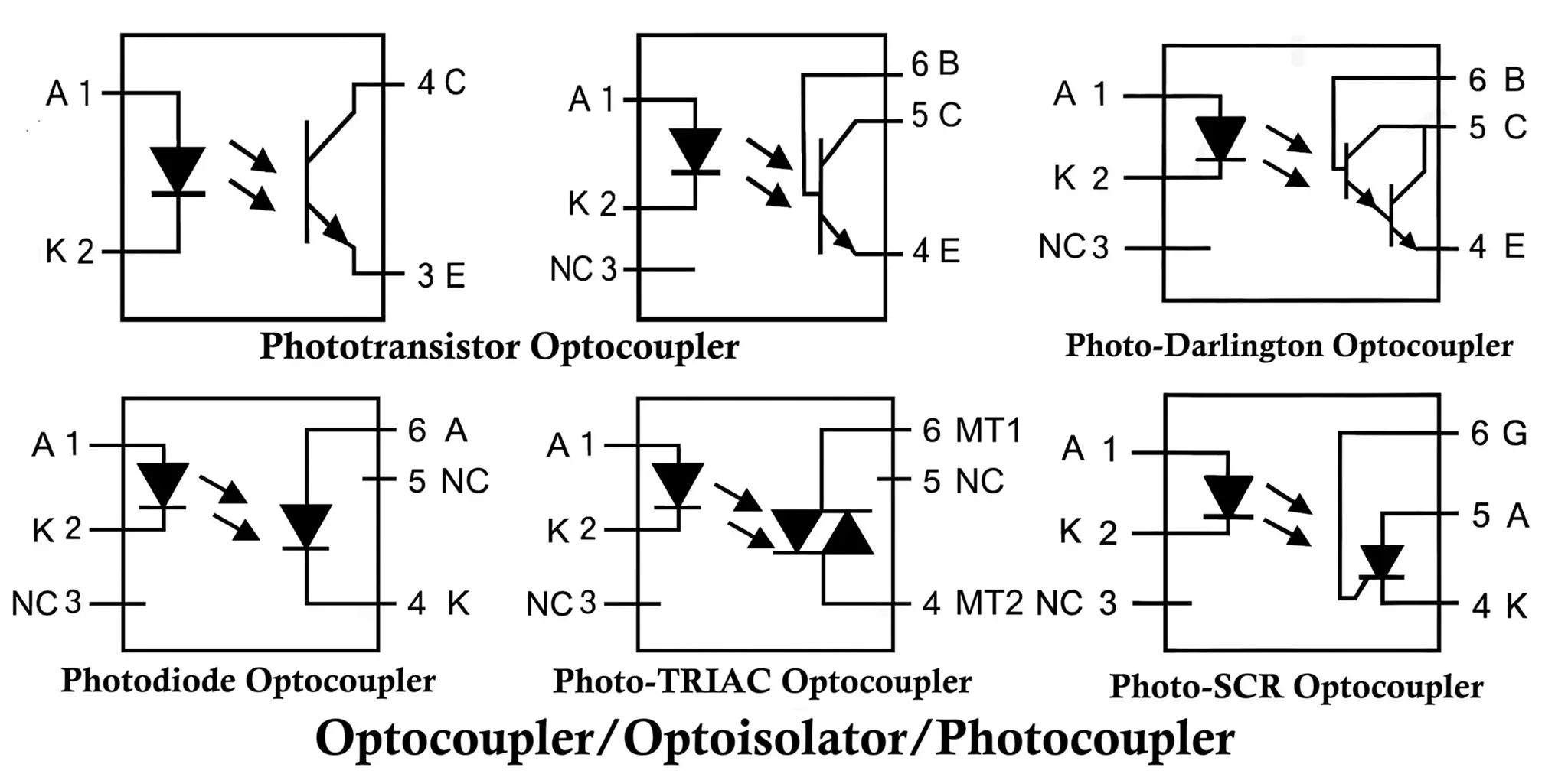
1. Phototransistor Optocoupler
In this type, a phototransistor serves as the output device. These optocouplers are typically unidirectional, making them suitable for DC applications. The phototransistor can be either NPN or PNP. Optocouplers are available in 4-pin and 6-pin IC packages.
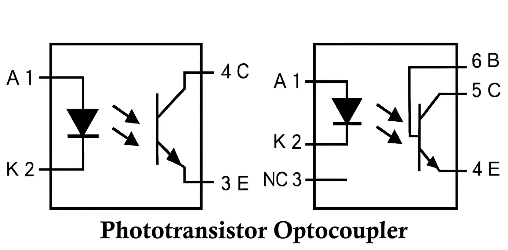
- 4-pin Configuration: Simple operation with standard input/output connections.
- 6-pin Configuration: Includes two additional terminals—Pin #3 is NC (Not Connected), while Pin #6 is the phototransistor’s base, which allows adjustment of sensitivity (if unused, it is typically grounded).
Applications: DC isolation, digital signal transmission
Current Transfer Ratio (CTR): ~100–300%
Speed: Moderate (microsecond range)
Examples: PC817, 4N35, H11L1, H11F1
2. Photodarlington Optocoupler
These optocouplers use a photodarlington transistor at the output for significantly increased current gain and sensitivity. Typically housed in a 6-pin IC, the pin configuration is:
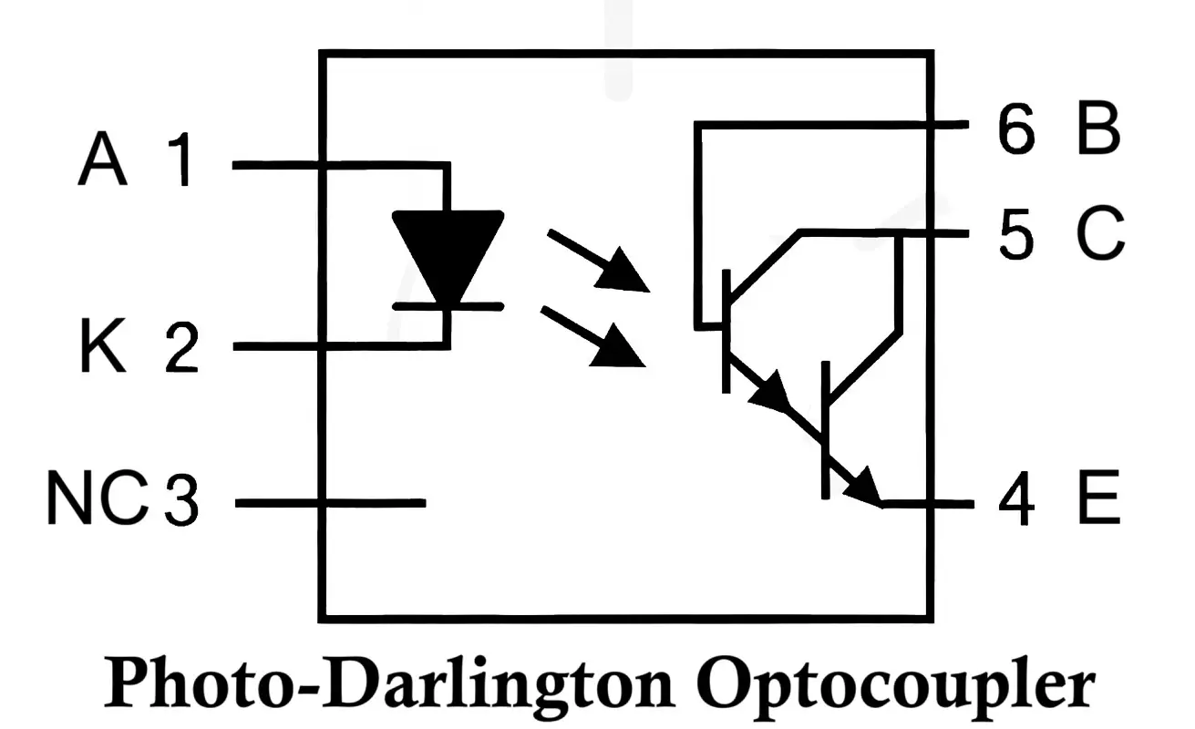
- Pin #1: Anode (LED)
- Pin #2: Cathode (LED)
- Pin #3: NC
- Pin #4: Emitter (Photodarlington)
- Pin #5: Collector
- Pin #6: Base (for sensitivity adjustment)
A photodarlington consists of two transistors connected in a Darlington pair configuration, doubling the gain and making it ideal for applications that require high amplification in DC circuits.
Applications: Low-power control circuits needing high sensitivity
CTR: ~500–600%
Speed: Slower than standard phototransistor types
Examples: 4N32, 4N33, H11B1, H11B2
3. PhotoTRIAC Optocoupler
Here, a PhotoTRIAC serves as the photosensor. The opto-TRIAC enables bidirectional switching when illuminated, making it suitable for both AC and DC circuits, though typically used for AC switching applications.
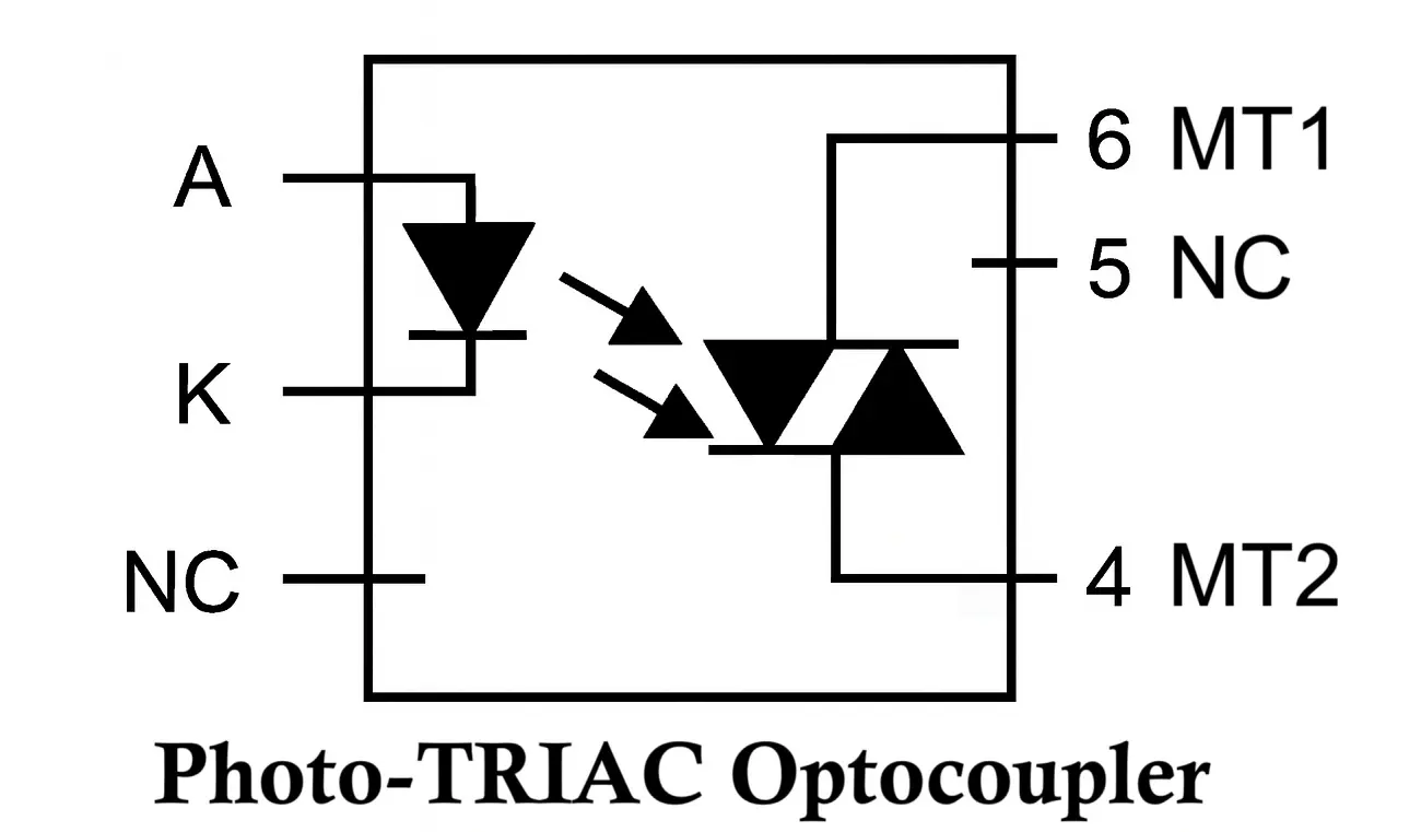
- Pin #1: Anode (LED)
- Pin #2: Cathode (LED)
- Pin #3: NC
- Pin #4: MT2 (Main Terminal 2)
- Pin #5: NC
- Pin #6: MT1 (Main Terminal 1)
Since the PhotoTRIAC operates purely in switching mode, there is no amplification involved.
Applications: AC load control, light dimmers, heating systems
Examples: MOC3020, MOC3041, MOC3062, MOC3051
4. PhotoSCR Optocoupler
A PhotoSCR (Silicon Controlled Rectifier) is used as the photosensor in this type, allowing controlled switching in high-power AC applications. Typically found in a 6-pin IC, the configuration includes:
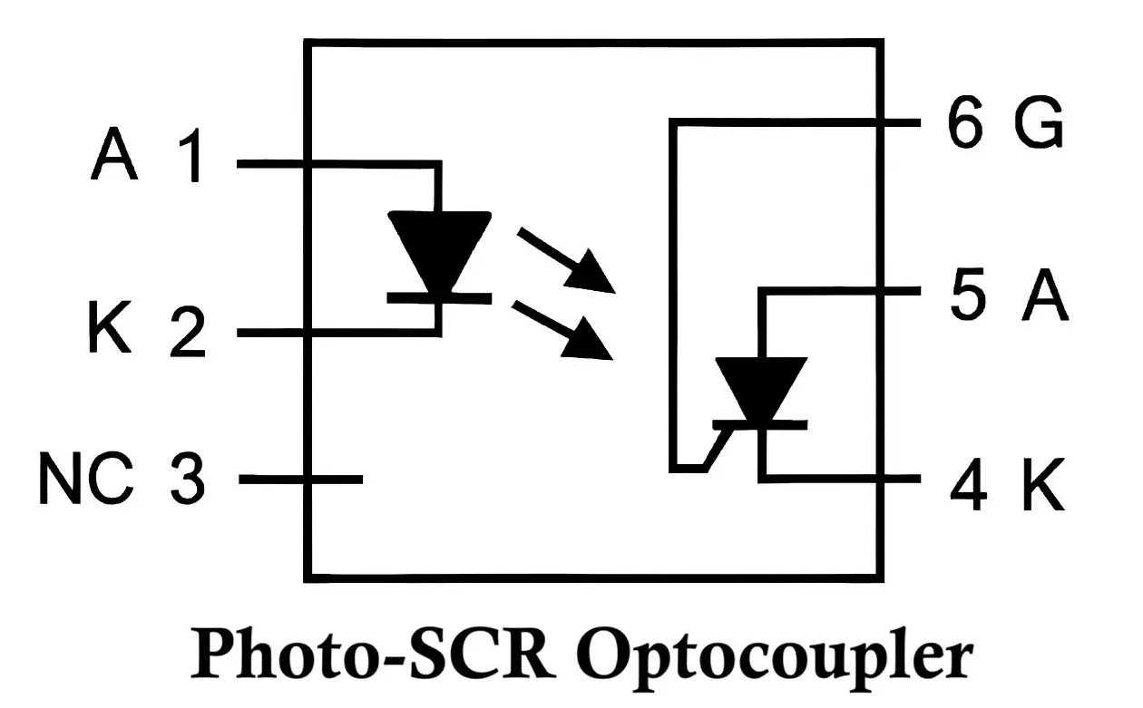
- Pin #1: Anode (LED)
- Pin #2: Cathode (LED)
- Pin #3: NC
- Pin #4: Cathode (PhotoSCR)
- Pin #5: Anode (PhotoSCR)
- Pin #6: Gate (PhotoSCR)—used to adjust sensitivity
The PhotoSCR operates as a unidirectional controlled switch triggered by light, and the gate terminal can further regulate sensitivity.
Applications: AC motor control, power switching
Examples: IL400, 4N39, 4N40, H11C1
5. Photodiode Optocoupler
A Photodiode Optocoupler (Photocoupler / Optoisolator) consists of an LED as the input light source and a photodiode as the photosensor, enabling high-speed, linear, and precise signal transmission with galvanic isolation. Typical pin configuration (6-pin IC):
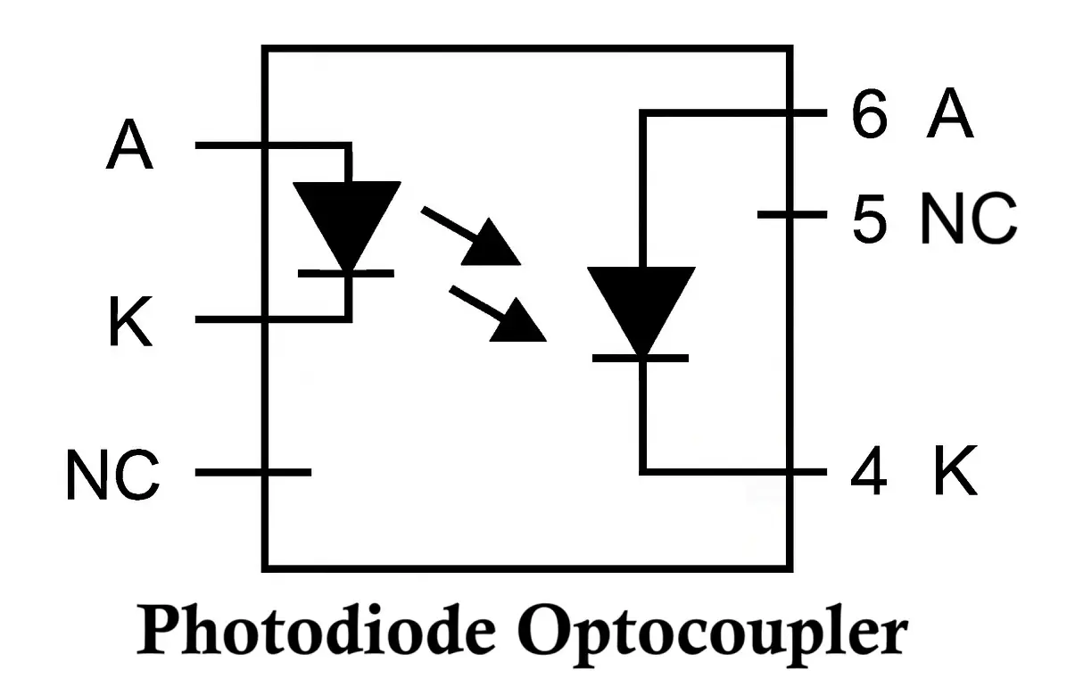
- Pin #1: Anode (LED)
- Pin #2: Cathode (LED)
- Pin #3: NC (Not Connected)
- Pin #4: Anode (Photodiode)
- Pin #5: Cathode (Photodiode)
- Pin #6: NC (Not Connected)
Applications: Analog signal isolation, high-speed digital isolation, medical instrumentation, precision analog measurements, isolated power supplies and motor drives.
Examples: ACPL-790J, ACPL-M61L, IL300
6. High-Speed Logic Gate Optocoupler
These optocouplers are specifically designed for high-frequency digital applications and include a built-in logic gate with an open-collector output.
- Speed: Up to 10 Mbps data rates
- Common-Mode Rejection (CMR): Very high (5–10 kV/μs)
Applications: High-speed digital signal isolation
Examples: 6N137, HCPL-2630/2631 series
Advantages of Optocoupler (Photocoupler / Optoisolator)
- Electrical Isolation:
- Provides complete electrical separation between input and output.
- Protects sensitive control circuitry from high voltages and spikes.
- Noise Immunity:
- Prevents noise, voltage surges, and ground loops from propagating from the power side to the control side.
- Fast Switching:
- Capable of fast signal transmission with low delay, especially with photodiode or photo-IC-based optocouplers.
- Compact and Simple:
- Integrates both LED and photodetector in a small, easy-to-use package.
- Wide Operating Voltage Range:
- Suitable for interfacing low-voltage microcontrollers to high-voltage industrial devices.
Disadvantages of Optocoupler (Photocoupler / Optoisolator)
- Limited Bandwidth:
- Optocouplers are generally slower than other forms of signal isolation (e.g., transformers or capacitive isolators), especially for analog signals.
- Temperature Sensitivity:
- Performance may degrade at high temperatures due to LED and phototransistor characteristics.
- Aging Effect:
- LEDs and photodetectors can degrade over time, reducing reliability.
- Limited Current Transfer Ratio (CTR):
- The ratio of output current to input current is finite and may vary significantly with temperature and device age.
- Non-linearity in Analog Applications:
- Optocouplers are not ideal for analog signal transmission because of non-linear behavior.
Applications of Optocoupler (Photocoupler / Optoisolator)
1. Electrical Isolation in Communication
- Purpose: Prevents high voltage from affecting low-voltage circuits.
- Example: Isolating microcontrollers from power electronics, such as in industrial automation systems, where the controller side operates at logic levels (e.g., 3.3V/5V) and the power side controls high voltage motors or relays.
2. Switching Power Supplies
- Purpose: Provide feedback from the output side to the controller while maintaining isolation.
- Example: In a switching power supply (SMPS), optocouplers relay the output voltage status back to the control circuit, helping to regulate the output voltage precisely.
3. Microcontroller Interfacing
- Purpose: Protect microcontroller inputs from voltage spikes or ground loops.
- Example: When a microcontroller reads signals from external sensors or devices operating at different voltages or in noisy industrial environments.
4. Signal Isolation in Data Communication
- Purpose: Prevent ground loops and noise interference during data communication.
- Example: Optical isolation is used in RS-232, RS-485, or CAN bus communication lines in industrial environments to avoid signal degradation and data corruption.
5. Motor Control
- Purpose: Isolate low-voltage control logic from high-voltage motor driving circuits.
- Example: An optocoupler allows a microcontroller to control a power MOSFET or IGBT for driving large motors without direct electrical connection, ensuring safety.
6. Industrial Automation
- Purpose: Protect sensitive electronics in harsh industrial environments.
- Example: Isolating PLC (Programmable Logic Controller) inputs and outputs from external high-voltage actuators, sensors, and machinery to prevent damage due to voltage surges.
7. Safety Applications
- Purpose: Prevent electric shock or equipment damage by providing isolation between user-accessible circuits and high-voltage sections.
- Example: Medical devices where patient contact circuits are isolated from the rest of the electronics for patient safety.
8. Pulse Signal Transmission
- Purpose: Accurately transmit pulse signals across isolated circuits.
- Example: In digital logic systems or communication lines where fast, isolated switching is required, such as in encoder signal transmission.
9. Audio Equipment
- Purpose: Eliminate hum and noise by isolating the ground of different audio circuit sections.
- Example: In audio interfaces, opto-isolators can transmit audio signals without introducing ground loop hum or electrical interference.
10. Power Line Communication (PLC) Systems
- Purpose: Enable communication between devices over power lines while isolating the control circuits.
- Example: Home automation systems where optocouplers ensure safe data communication over AC power lines.
Conclusion
Optocouplers (also known as an optoisolator or Photocoupler) are indispensable in electronic circuit design where signal isolation, noise reduction, and system protection are critical. While they have limitations such as bandwidth and aging, their ability to maintain robust isolation makes them ideal for industrial, medical, and communication applications.
By understanding the construction, working principles, advantages, disadvantages, and applications, engineers can effectively design circuits that maintain safety and performance even in harsh electrical environments.
Difference Between Photodiode, Phototransistor and Photoresistor
Types of Diodes with Symbol, Definition, Working and Applications
Types of Transistors: Classification (BJT, JFET, MOSFET & IGBT)
