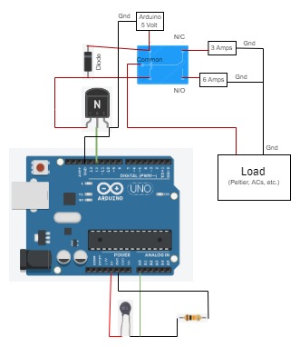
Hello friends, Do you know how to switch between two power supplies or current sources using a Current Switching Circuit using Arduino and Relays? Welcome to another interesting article, suppose you want to operate a device that can be operated based on the room temperature or a temperature inside the device, let’s understand this with a […]
OP-AMP tutorial
In this blog you can find opamp tutorial and circuits like differentiator integrator, summing amplifier and many more circuit. Operational amplifier basics detailed explanation and working of each circuit.
An operational amplifier is a DC-coupled high-gain electronic voltage amplifier amplifier that has high gain, differential input, high input resistance, and low output resistance.
There are mainly two types of opams amplifiers inverting amplifiers and others one is non inverting amplifier.
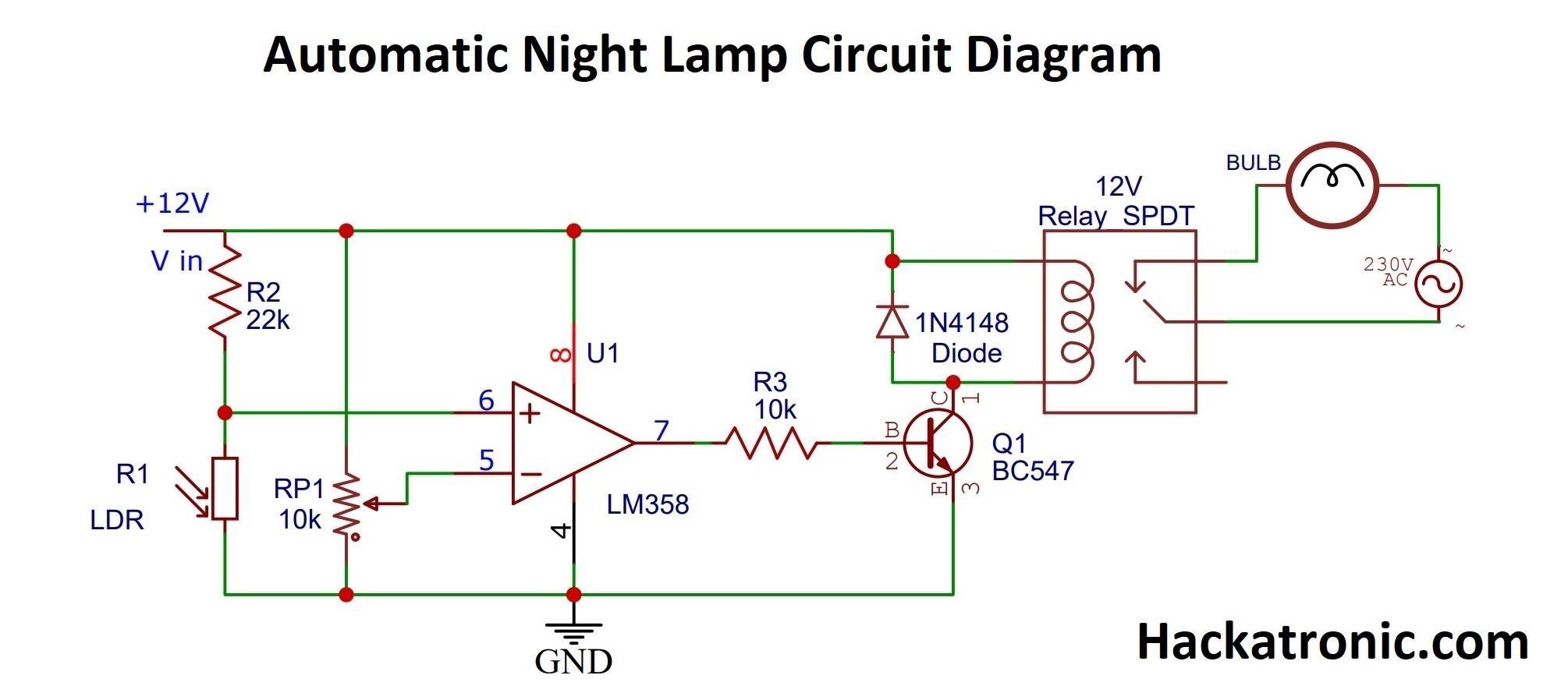
Automatic Night Lamp Circuit Diagram by LDR & LM358 OPAMP
This article explains an automatic night lamp circuit diagram using LDR and LM358 OPAMP which automatically turns the LEDs ON at night and OFF when it is daytime. The sensing part which is being used for detecting the light is a Light Dependent Resistor (LDR). The resistance of LDR depends on the light incident on […]
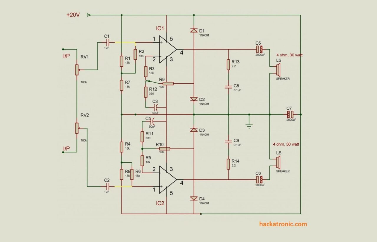
Stereo Amplifier Circuit 20W + 20W
If you are looking for a first-class 40-watt music stereo amplifier, then look no further. High output efficiency, negligible hum, low harmonic distortion, clarity of the output sound, compact (modular) size, and low cost are some of the key features of this fully solid-state integrated Hi-Fi stereo amplifier which is capable of delivering an output […]
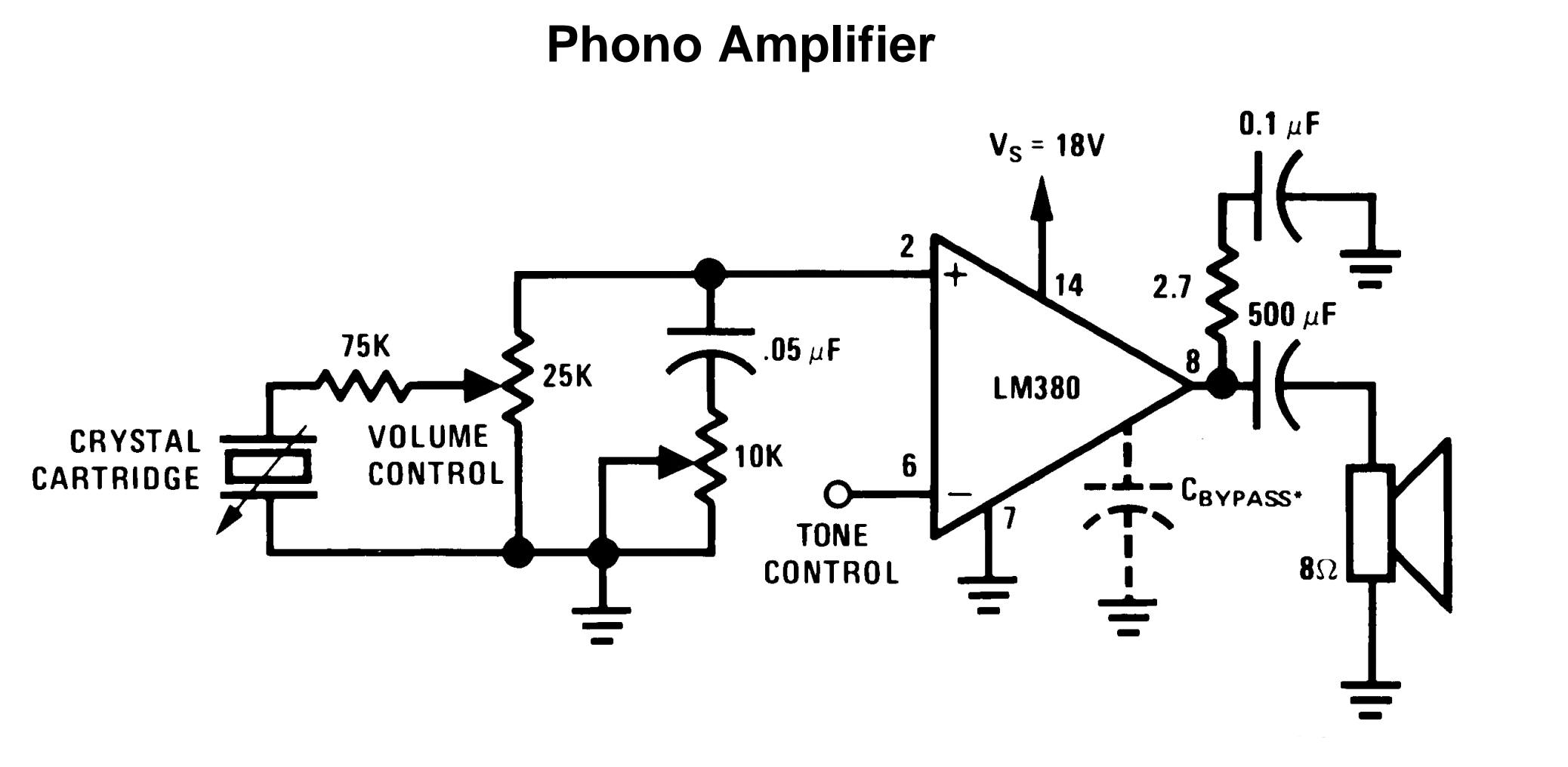
LM380 Audio Power Amplifier Circuit And it’s Working
The LM380 is an audio power amplifier for consumer application. Its internal gain is fixed to 14dB in order to keep the system cost minimum. A unique input stage allows inputs to be referenced with the ground. The output gets automatically self-centered to one half the supply voltage. The output amplifier is short circuit proof […]
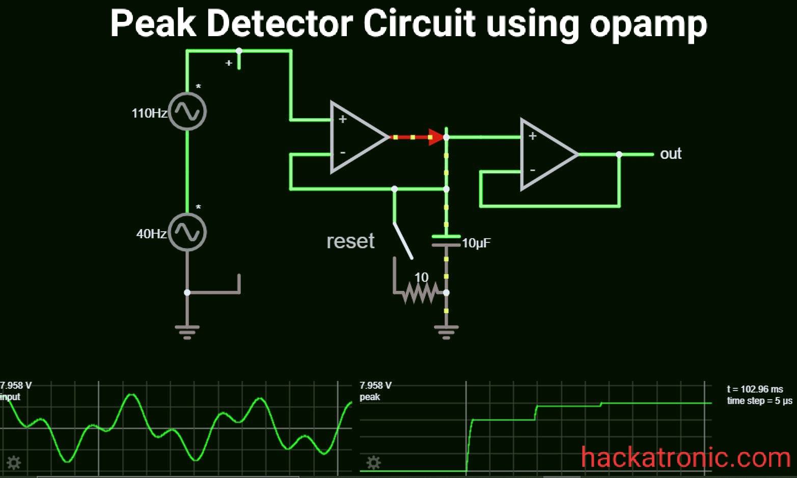
Peak Detector Circuit using OPAMP
Here is the circuit diagram of a peak detector circuit using opamp. A peak detector circuit is used to determine the maximum (peak) value of an input signal. It stores the maximum value of the input signal for a very long interval of time. In many applications we need to measure the maximum value of […]
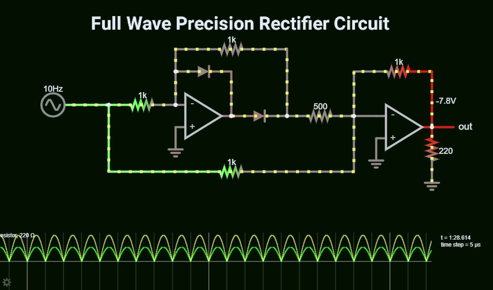
Precision Rectifier Circuit using OPAMP working and applications
The precision rectifier is a type of rectifier that converts the AC signal to DC without any loss of signal voltage. In a precision rectifier circuit using opamp, the voltage drop across the diode is compensated by the opamp. In a Diode voltage drop is around 0.6V or 0.7V. Also, this circuit can be made […]
