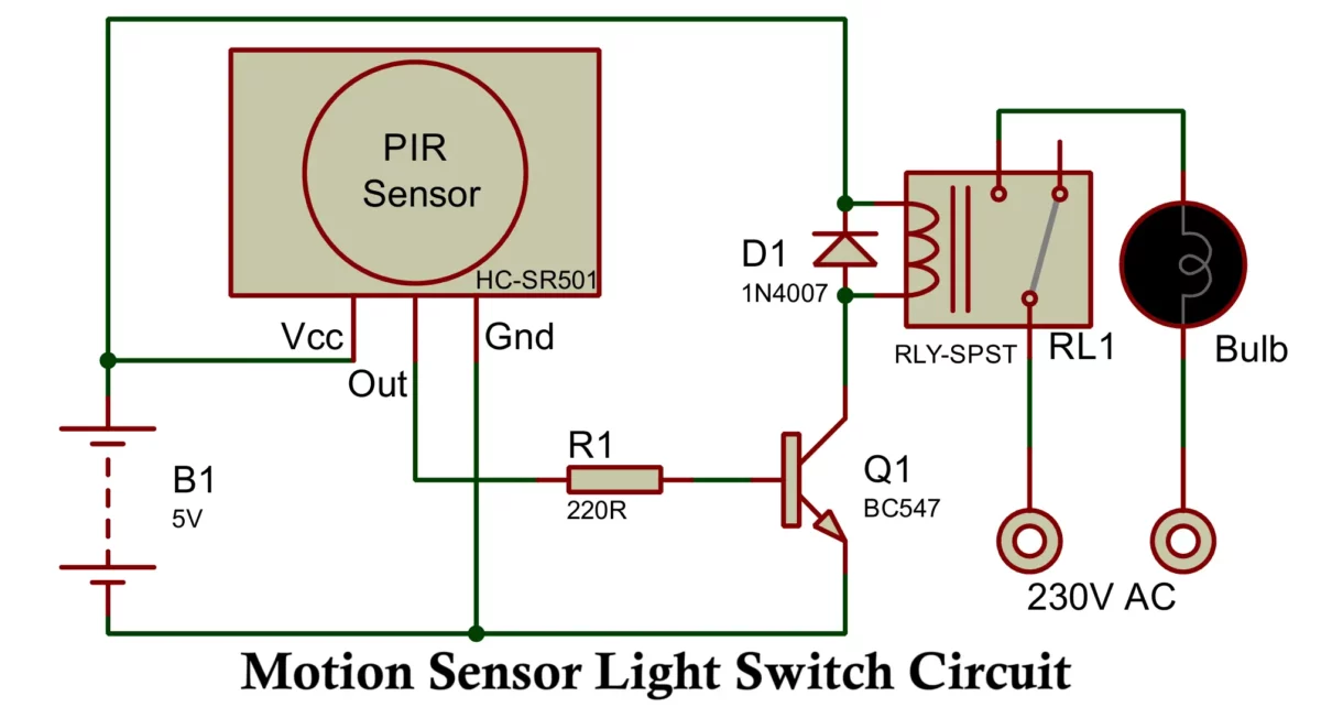
Automatic Cut Off Battery Charger Circuit
DC Power Supply Electronics project Electronics tutorial Protection Circuits

12V Automatic Cut Off Battery Charger Circuit Using Relay

This article details the construction and working of an Automatic Cut-Off Battery Charger Circuit using common components such as a relay, transistor, potentiometer (pot), LED, diodes, and resistors. Battery chargers with automatic cut-off functionality ensure batteries do not overcharge, enhancing their life span and performance. This circuit charges the battery in its Normally Closed (NC) […]

12V Auto Cut Off Battery Charger Circuit
DC Power Supply Electronics project Electronics tutorial Power supplies Protection Circuits

12V Auto Cut-Off Battery Charger Circuit Diagram by MOSFET

Battery chargers with automatic cut-off functionality are vital for protecting batteries from overcharging, enhancing their lifespan, and ensuring efficient operation. This guide explains how to build a simple 12V auto cut-off battery charger circuit using commonly available components, including a TL431 voltage reference IC, a MOSFET IRFZ44N, LEDs for status indication, and other basic components. […]

Battery Level Indicator
Circuit Designing Electronic devices Electronics project Electronics tutorial Integrated circuits (ICs) Protection Circuits

LM3915 LED Battery Voltage Level Indicator Circuit Diagram

In this article, you will learn to build LM3915 battery voltage level indicator. The LM3915 is a popular integrated circuit (IC) used in projects that require visual feedback on voltage levels. It’s widely applied in devices like battery monitors, audio level meters, and power supply indicators. This IC lights up a series of LEDs to show […]

SG3525 Inverter Circuit
Circuit Designing Electronics project Electronics tutorial Inverters PCB Designing PCB Manufacturing Power supplies

SG3525 PWM Inverter Circuit Diagram and it’s Working

The SG3525 is a versatile PWM (Pulse Width Modulation) controller IC commonly present in inverter circuits to convert DC to AC at either 50Hz or 60Hz. Here’s a PWM based SG3525 inverter circuit with working. 1. Components Required: SG3525A PWM Controller IC N-channel MOSFETs (e.g., IRF3205) or IGBTs Transformers (Center-tapped, depending on the required output […]

DC-DC Buck & Boost Converter Circuit
Circuit Designing DC Power Supply Electronics project Electronics tutorial

DC-DC Buck-Boost Converter Circuit using UC3843 IC

The Universal DC-DC Buck & Boost Converter Circuit with UC3843 is a versatile circuit that can be used to either boost or buck a DC voltage, depending on the specific configuration. The UC3843 is a popular PWM (Pulse Width Modulation) controller IC used for these types of converters because of its high performance and ease […]

Boost Converter Circuit Using 555 Timer
555 timer IC DC Power Supply Electronics project Electronics tutorial MOSFETs Power supplies

DC-DC Boost Converter Circuit Using 555 Timer

A boost converter circuit is a DC-DC power converter that steps up voltage from its input to its output while stepping down current. It’s widely used in applications where a higher output voltage is required from a lower input voltage, such as in battery-operated devices. One of the simplest ways to design a boost converter […]