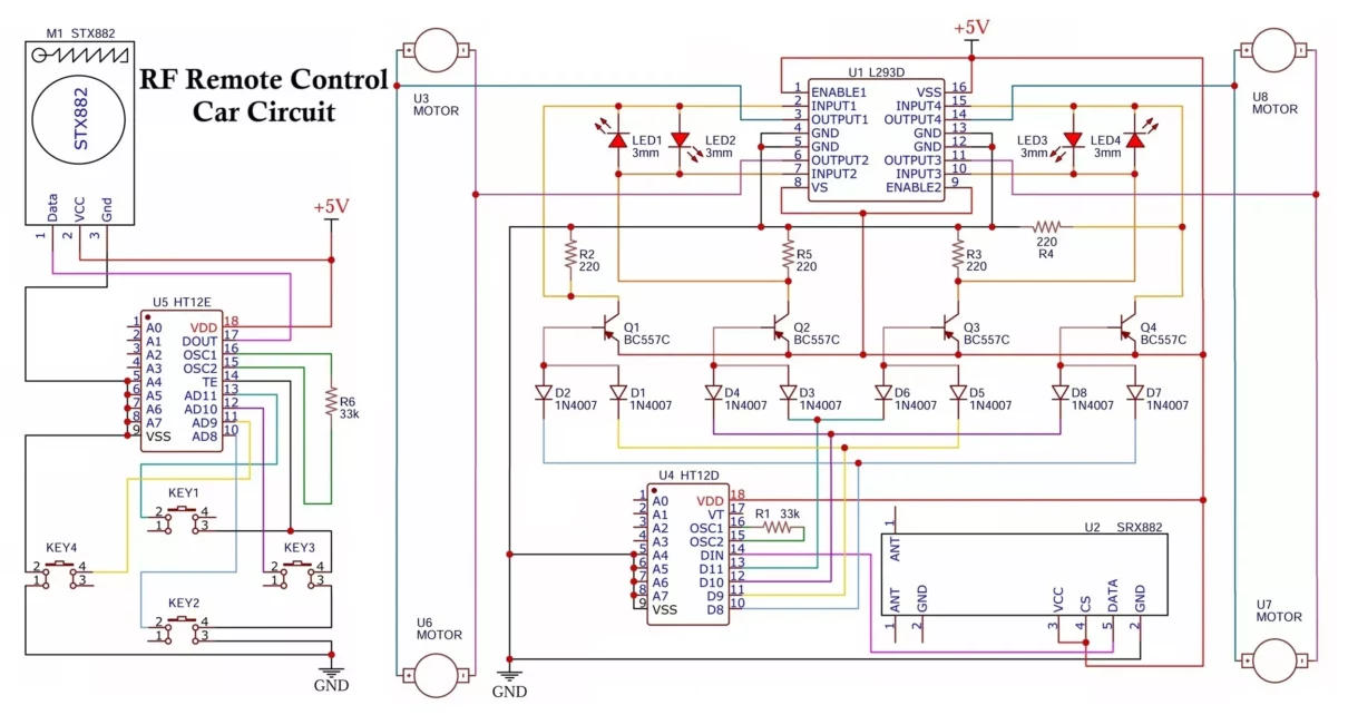
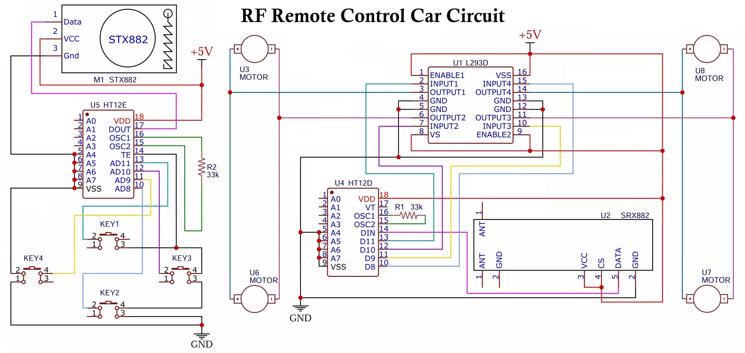
Creating a wireless remote-control car using 433MHz RF modules is a classic electronics project. This guide explores a fully functional DIY 433MHz RF Remote Control Car Circuit using the HT12E/HT12D encoder-decoder pair, STX882/SRX882 RF modules, L293D motor driver, and BC557C transistors. We’ll also delve deep into how the transistors and diodes manage motor control and visual feedback using LEDs.
Remote Control Car Circuit Components
ICs & Modules
- HT12E: Encoder IC
- HT12D: Decoder IC
- STX882: 433MHz RF Transmitter Module
- SRX882: 433MHz RF Receiver Module
- L293D: Dual H-Bridge Motor Driver
- BC557C: PNP Transistors × 4
Discrete Components
- 1N4007 Diodes: 8 pcs
- LEDs: 4 pcs (3mm)
- Resistors:
- R1, R6: 33k (for oscillators of HT12E and HT12D)
- R2, R3, R4, R5: 220Ω (base resistors and LED current limiters)
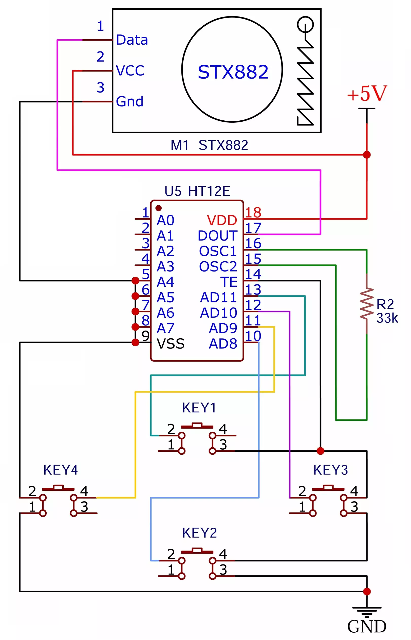
Transmitter Circuit Description
- HT12E acts as the heart of the transmitter and encodes the four digital inputs (KEY1 to KEY4).
- Each push button connects to the DATA inputs (AD8–AD11) of the HT12E.
- Set the A0 to A7 (address pins) either LOW or HIGH and mirror the same configuration on the receiver.
- Connect OSC1 and OSC2 through a 33kΩ resistor (R6) to generate the internal oscillator frequency.
- Tie the TE (Transmit Enable) pin LOW to enable transmission.
- When you press any button, the DOUT pin outputs the encoded data.
- The DOUT pin of the HT12E sends this data to the Data pin of the STX882, which transmits the modulated signal at 433 MHz.
- Connect an external wire antenna to the ANT pin of the STX882 to improve the transmission range.
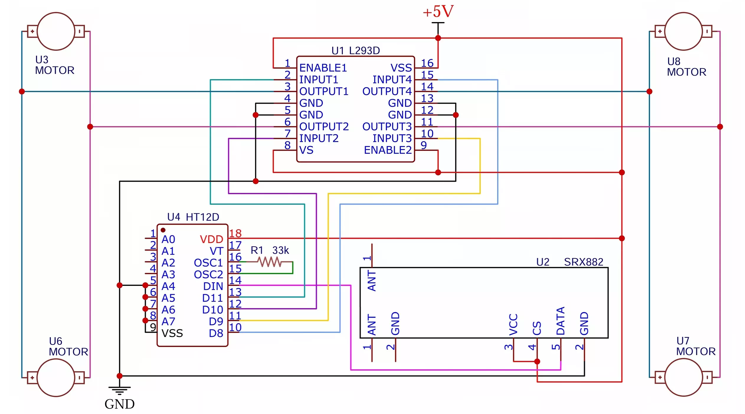
Receiver Circuit Description
- SRX882 receives the transmitted RF signal and outputs it via Data pin to DIN of HT12D.
- HT12D decodes the signal. The address bits A0 to A7 are configured to match HT12E.
- A 33k resistor (R1) is connected between OSC1 and OSC2 for frequency generation.
- When valid data is received, VT (Valid Transmission) pin goes HIGH.
- The data pins D8 to D11 of HT12D reflect the logic levels from the buttons pressed on the transmitter.
Diode Transistor LED Interface Explanation
Each output pin (D8-D11) from HT12D connects to two diode transistor and LED interface that controls each channel of the L293D. You can use simple receiver circuit, if you want LED indication and some protection use this one.
Detailed Diode and Transistor Configuration
Each HT12D output:
- Is connected to two 1N4007 diodes leading to two separate BC557C PNP transistors (Q1 to Q4).
- The cathode of each diode is connected to HT12D outputs.
- The anode is connected to the base of a BC557C via a 1N4007 diode.
- The collector is connected to ground through a 220Ω resistor (R2–R5).
- The emitter is connected to +5V, and the collector goes to:
- The control input of L293D (INPUT1–INPUT4).
- Two back-to-back LEDs with 220Ω resistor to GND for visual feedback.
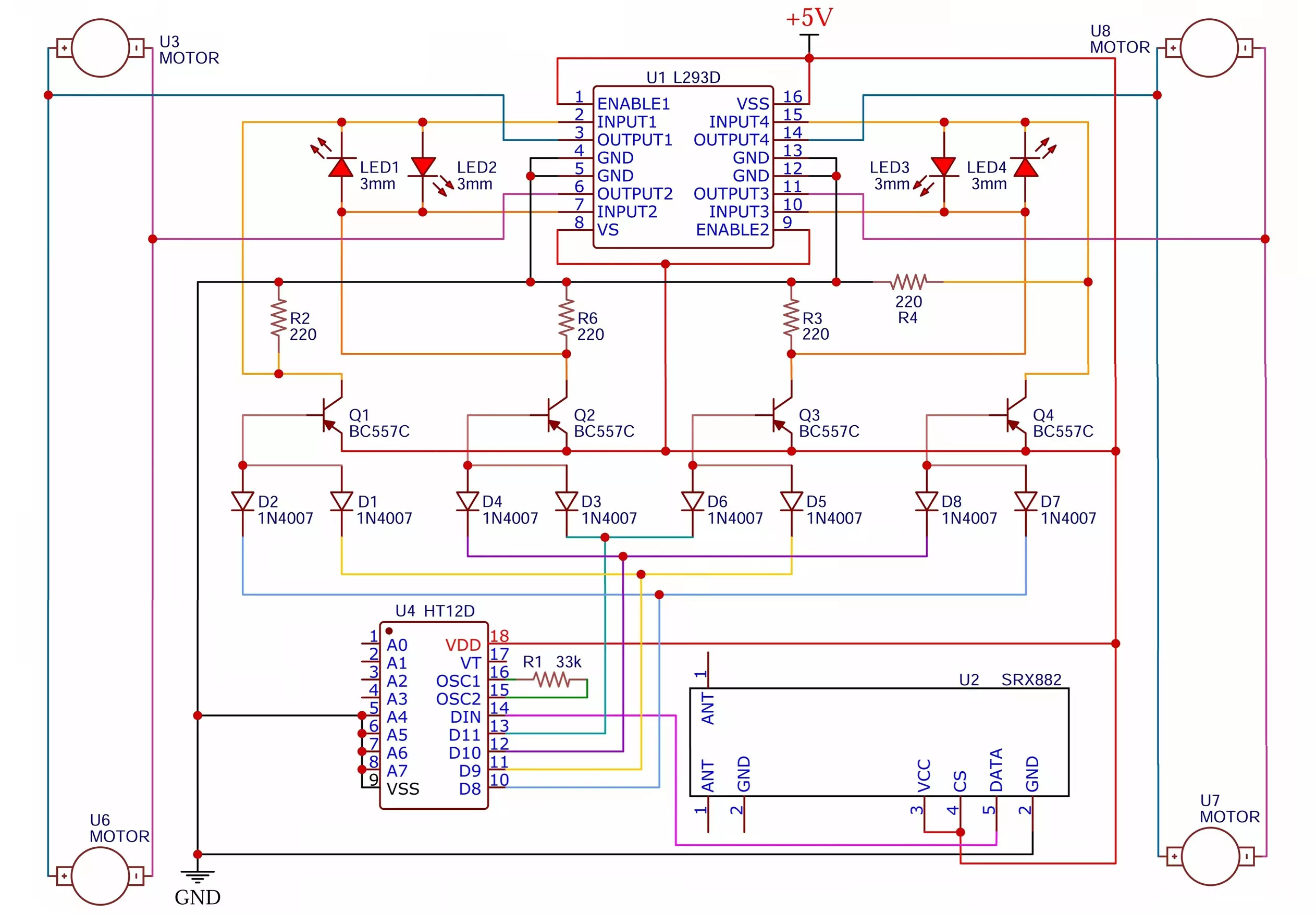
Working of Transistors in This Circuit
- BC557C is a PNP transistor, so it turns ON when its base is LOW relative to the emitter (+5V).
- When an HT12D output goes LOW, it pulls the base of the corresponding transistor LOW through the diode network.
- This turns the transistor ON, allowing current from the emitter to flow through the collector → activating the L293D control input.
- When the transistor conducts, LEDs in reverse series light up, indicating activity on that motor channel.
L293D Motor Driver Control Logic
The L293D is a dual H-bridge motor driver IC. Each side (channel) controls one motor using two inputs and one enable:
Control Pins for 2 Motors per Side:
- INPUT1 & INPUT2 + ENABLE1 → MOTOR 1,3
- INPUT3 & INPUT4 + ENABLE2 → MOTOR 2,4
In this design:
- Each HT12D output controls two INPUT pins of the corresponding motor channel via transistor switches.
- This ensures the motor will rotate only if the transistor is ON and HT12D output is valid for that channel
Motor Operation Logic Table
| HT12D Outputs | Transistor (Qx) | L293D Input/Enable | Motor State |
|---|---|---|---|
| LOW | ON (conducting) | HIGH | Motor rotates |
| HIGH | OFF | LOW | Motor stops |
LED Indicator Working
- The back-to-back LEDs serve two purposes:
- Direction indication (based on polarity)
- Visual confirmation of transistor conduction (control activation)
- As current flows through one LED and not the other, the lit LED shows which transistor is ON and thus which direction or channel is active.
Power Supply Connections
- +5V is used for logic ICs (HT12E, HT12D), L293D control, and transistors.
- VSS, GND are common grounds.
- VSS on L293D is the motor supply (can be 6V–12V for motors).
- Ensure decoupling capacitors are placed near ICs for stability.
Working of Remote-Control Car Circuit in Short
- User presses a button on the transmitter → HT12E encodes data → STX882 transmits.
- SRX882 receives the RF signal → HT12D decodes it.
- Output of HT12D activates specific transistor switches via diodes.
- Transistors pull up control lines of L293D, enabling motor channels.
- Motors rotate based on active control inputs.
- LED indicators light up to show the active motor paths.
Advantages
- Simple & Cost-Effective
Uses low-cost, easily available components, ideal for beginners and hobbyists. - Wireless Freedom
RF communication allows remote operation up to 200 meters with proper antenna setup. - Modular Build
Separated transmitter/receiver sections simplify troubleshooting and upgrades. - Built-in Visual Feedback
Status LEDs give instant indication of transmission activity. - Efficient Motor Control
The L293D dual H-bridge handles bidirectional motor control effectively. - Future-Proof & Expandable
Add more channels or shift to a microcontroller-based system later.
Disadvantages
- No Communication Security
Signal is unencrypted—open to interference or overlap from other 433MHz devices. - Limited Unique Pairing
Only 256 address combinations (8 bits) with HT12E/HT12D. - One-Way Only
No return signals or feedback from receiver to transmitter. - Data Rate Constraints
Suitable for digital signals only—no analog or advanced control schemes. - Range Affected by Obstacles
Range may drop significantly in environments with physical barriers.
Applications
- Hobby RC Cars & Robots
Perfect learning tool for electronics and wireless systems. - Home Automation Projects
Control lights or appliances via RF relay switching. - Remote-Controlled Toys
Simple RC boats, toy cars, or small robots. - Wireless Device Activation
Use transmitter buttons to wirelessly trigger alarms or garage doors. - Basic Security Systems
Panic buttons or simple RF-based lock/unlock mechanisms. - Small-Scale Industrial Control
RF remote toggling of motors or devices indoors.
Conclusion
This DIY 433MHz RF Remote Control Car circuit shows how to wirelessly control DC motors using basic components like HT12E/HT12D, STX882/SRX882, and L293D. It combines RF communication, transistor control, and LED indicators, making it a great starting point for remote-controlled vehicles or automation projects. This can be extended to 8-channel control with multiple encoder/decoder setups. Add sensors or feedback for advanced versions. While it’s not the most secure or complex system, it’s easy to build, affordable, and perfect for beginners, students, and hobbyists.
BME680 and ESP8266 Based Indoor Air Quality Monitoring System
Types of Capacitors with Symbol, Classification and Applications
TDA2030 Audio Amplifier Circuit: Mono, Stereo and Bass Amplifier
