A carbon film resistor is one of the most widely used fixed resistors in electronic circuits. It belongs to the carbon-based resistor family, where resistance is obtained from a thin layer of carbon deposited on an insulating substrate. Due to its moderate cost, good stability, reasonable accuracy, and wide resistance range, the carbon film resistor became a standard choice in consumer electronics, industrial control circuits, and educational projects.
Carbon film resistors largely replaced carbon composition resistors because they offer better tolerance, lower noise, and improved temperature stability, while still remaining economical.
Carbon Film Resistor Symbol
In circuit diagrams, a carbon film resistor uses the standard resistor symbol, identical to other fixed resistors:
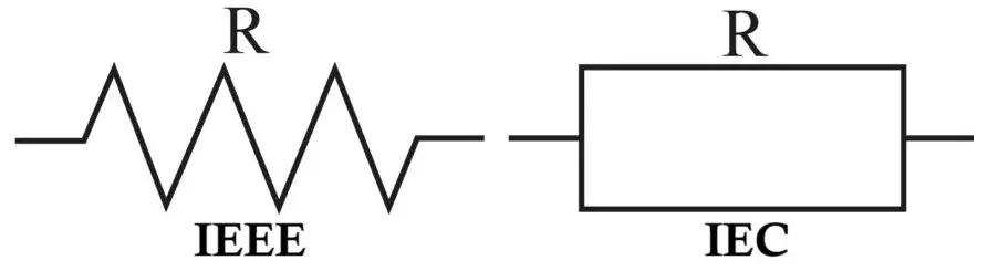
- Zigzag line (ANSI standard – commonly used in the USA)
- Rectangular box (IEC standard – widely used in Europe and India)
The symbol does not differentiate between carbon film, metal film, or wire-wound resistors; the type is identified from the BOM (Bill of Materials) or component specification.
Related Articles:
- Carbon Composition Resistor Construction, Working & Applications
- Types of Resistors with Symbol, Classification and Applications
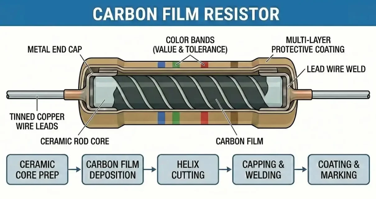
Construction of Carbon Film Resistor
The performance of a carbon film resistor is directly related to its layered construction process. Here are the main construction elements.
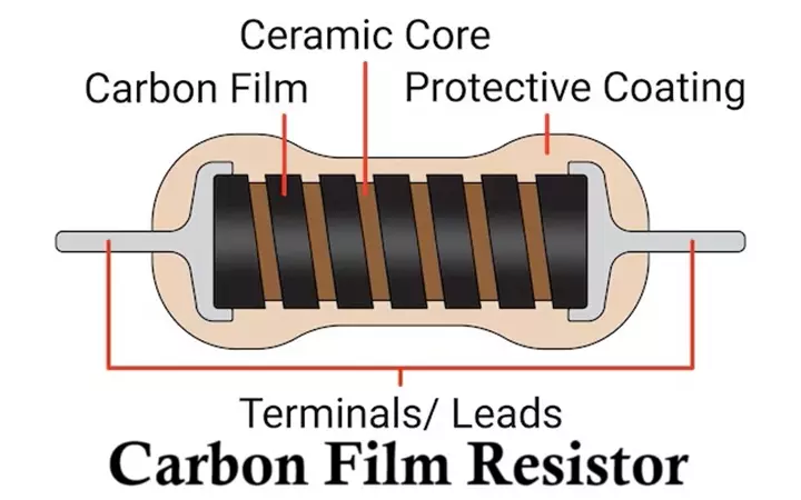
- Ceramic Core (Substrate)
- Made of high-purity alumina (Al₂O₃)
- Provides mechanical strength and excellent electrical insulation
- Acts as a stable base for the resistive layer
- Carbon Film Layer
- A very thin film of pure carbon deposited using chemical vapor deposition (CVD)
- Thickness of the carbon film determines the base resistance value
- Helical Groove (Spiral Cut)
- A precise spiral cut is made using laser trimming
- Increases the effective length of the current path
- Allows fine adjustment of resistance value
- Metal End Caps
- Attached at both ends of the ceramic rod
- Provide low-resistance electrical contact
- Axial Leads
- Usually tinned copper wires
- Enable easy through-hole mounting on PCBs
- Protective Coating
- Epoxy or lacquer coating
- Protects against moisture, dust, and mechanical damage
- Color bands printed on this coating
Working Principle of Carbon Film Resistor
The operation of a carbon film resistor is based on Ohm’s Law:
V = I×R
- When a voltage is applied across the resistor, an electric field is established.
- Electrons flow through the carbon film layer, which offers controlled resistance.
- The spiral cut forces electrons to travel a longer path, increasing resistance.
- Electrical energy is partially converted into heat due to collisions between electrons and carbon atoms.
- The resistor limits current flow and produces a voltage drop proportional to resistance.
Carbon film resistors are designed to operate safely within a specified power rating to prevent overheating and drift.
Electrical Characteristics
- Resistance Range
- Typically, from 1 Ω to 10 MΩ
- Wider range than carbon composition resistors
- Tolerance
- Common tolerances: ±2%, ±5%, ±10%
- Much better than carbon composition resistors (±20%)
- Temperature Coefficient (TCR)
- Typical TCR: −200 to −800 ppm/°C
- Resistance decreases slightly as temperature increases
- Power Rating
- Common ratings: 1/8 W, 1/4 W, 1/2 W, 1 W, 2 W
- Exceeding the rating leads to thermal damage or permanent drift
- Noise Performance
- Lower noise than carbon composition resistors
- Slightly noisier than metal film resistors
How to Read Carbon Film Resistor Value
Carbon film resistors use color bands to indicate resistance and tolerance.
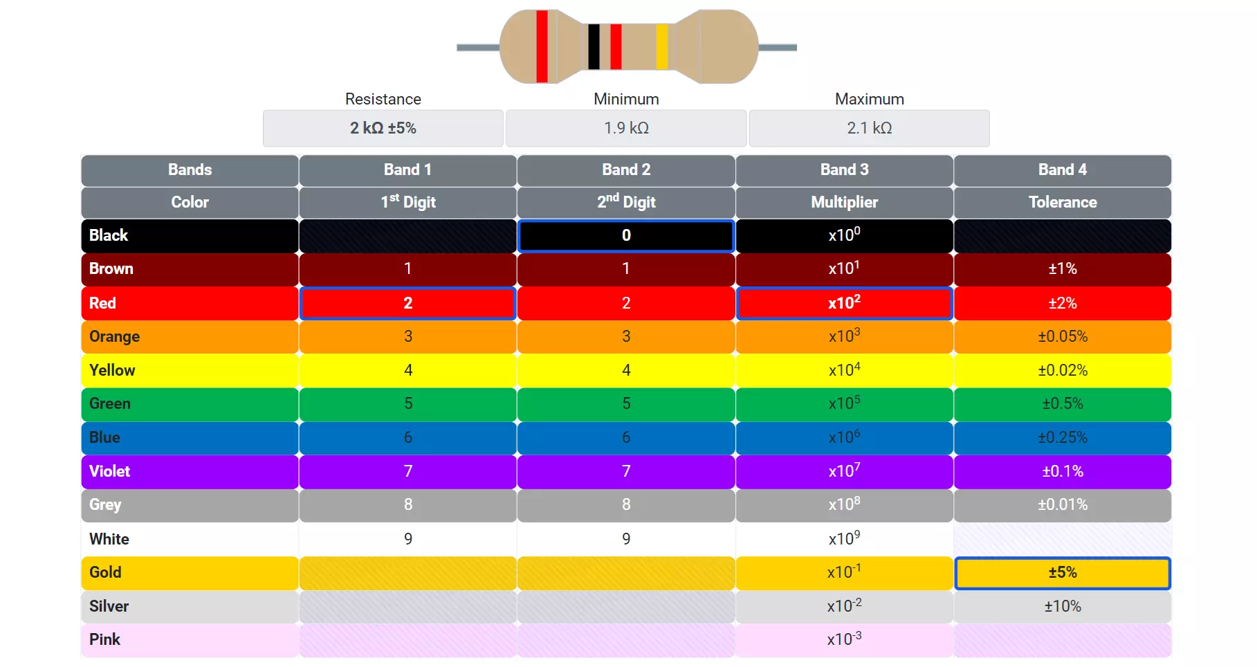
Four-Band Color Code
| Band | Meaning | Example (Brown-Black-Red-Gold) |
|---|---|---|
| 1 | First digit | Brown = 1 |
| 2 | Second digit | Black = 0 |
| 3 | Multiplier (×10ⁿ) | Red = ×100 |
| 4 | Tolerance (%) | Gold = ±5% |
Resistance = (10 × 100) = 1,000 Ω or 1 kΩ ±5%
Five-Band Color Code
Used for higher precision resistors (±2% or better):
- First three bands → significant digits
- Fourth band → multiplier
- Fifth band → tolerance
Types of Carbon Film Resistors
- Based on Power Rating
- Low-power carbon film resistors
- Medium-power carbon film resistors
- High-power carbon film resistors (up to a few watts)
- Based on Packaging
- Axial lead carbon film resistors
- Flame-proof carbon film resistors
- Fusible carbon film resistors
- Based on Accuracy
- Standard carbon film resistors (±5%, ±10%)
- Precision carbon film resistors (±2%)
Selection Criteria for Carbon Film Resistors
When selecting a carbon film resistor, the following factors must be considered:
- Resistance Value: Choose exact or nearest standard value from E-series
- Tolerance: ±5% is sufficient for general electronics, ±2% for control and sensing circuits
- Power Rating: Always select at least twice the calculated power dissipation, this improves reliability and lifespan
- Operating Temperature: Ensure resistor can handle ambient and self-heating temperatures
- Voltage Rating: Important for high-voltage applications
- Environmental Conditions: Moisture-resistant coating for humid environments
Advantages of Carbon Film Resistors
- Low cost and wide availability
- Better tolerance than carbon composition resistors
- Lower electrical noise
- Good long-term stability
- Wide resistance and power rating range
- Easy PCB mounting
Disadvantages of Carbon Film Resistors
- Inferior accuracy compared to metal film resistors
- Resistance drifts slightly with temperature
- Not suitable for high-precision or high-frequency circuits
- Limited power handling compared to wire-wound resistors
Applications of Carbon Film Resistors
Carbon film resistors are extensively used in:
- Consumer electronics (TVs, radios, chargers)
- Audio amplifiers and tone control circuits
- Power supply circuits
- Biasing networks in transistor circuits
- Voltage divider circuits
- Educational and DIY electronics projects
- General-purpose signal conditioning circuits
Comparison with Other Resistors
- Carbon Composition: Higher noise, lower stability
- Metal Film: Higher accuracy, lower noise
- Wire-Wound: High power, inductive behavior
Carbon film resistors provide a balanced trade-off between cost, performance, and reliability.
Summary Table
| Parameter | Carbon Film Resistor |
|---|---|
| Resistive Material | Carbon film |
| Construction Base | Ceramic rod |
| Resistance Range | 1 Ω to 10 MΩ |
| Tolerance | ±2% to ±10% |
| Power Rating | 1/8 W to 2 W |
| Temperature Coefficient | −200 to −800 ppm/°C |
| Noise Level | Medium |
| Cost | Low |
| Typical Applications | General electronics |
Conclusion
The carbon film resistor remains a workhorse component in modern electronics. While newer technologies such as metal film resistors offer superior precision, carbon film resistors still dominate cost-sensitive and general-purpose applications. Their reliable construction, reasonable accuracy, and wide availability make them indispensable in both learning environments and commercial electronic products.
Carbon Composition Resistor Construction, Working & Applications
Types of Resistors with Symbol, Classification and Applications
Types of Capacitors with Symbol, Classification and Applications
Light Dependent Resistor (LDR) / Photoresistor Circuit Diagram & Working
