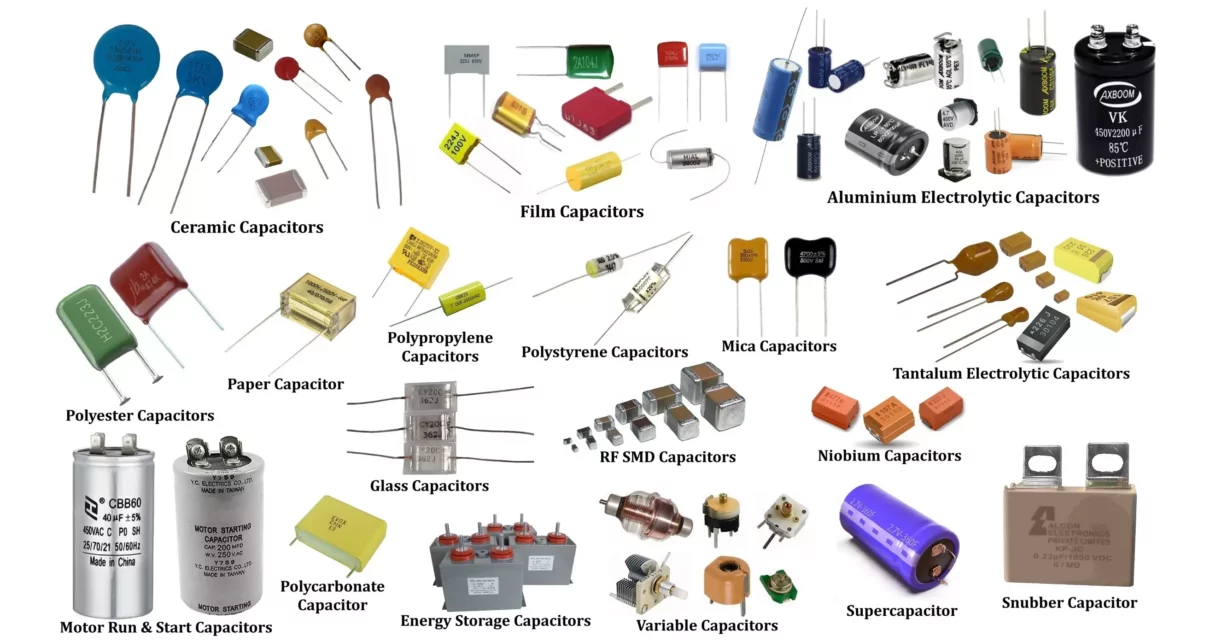
This guide provides an in-depth look at various types of capacitors, their Symbol, construction, working principles, advantages, disadvantages, and applications. Capacitors are essential components in electronic circuits, serving a wide range of applications such as energy storage, filtering, timing, and coupling. They are classified into three main categories: Fixed Capacitors, Variable Capacitors, and Special Purpose Capacitors. Each type has unique characteristics that determine its suitability for different applications.
1. Fixed Capacitors
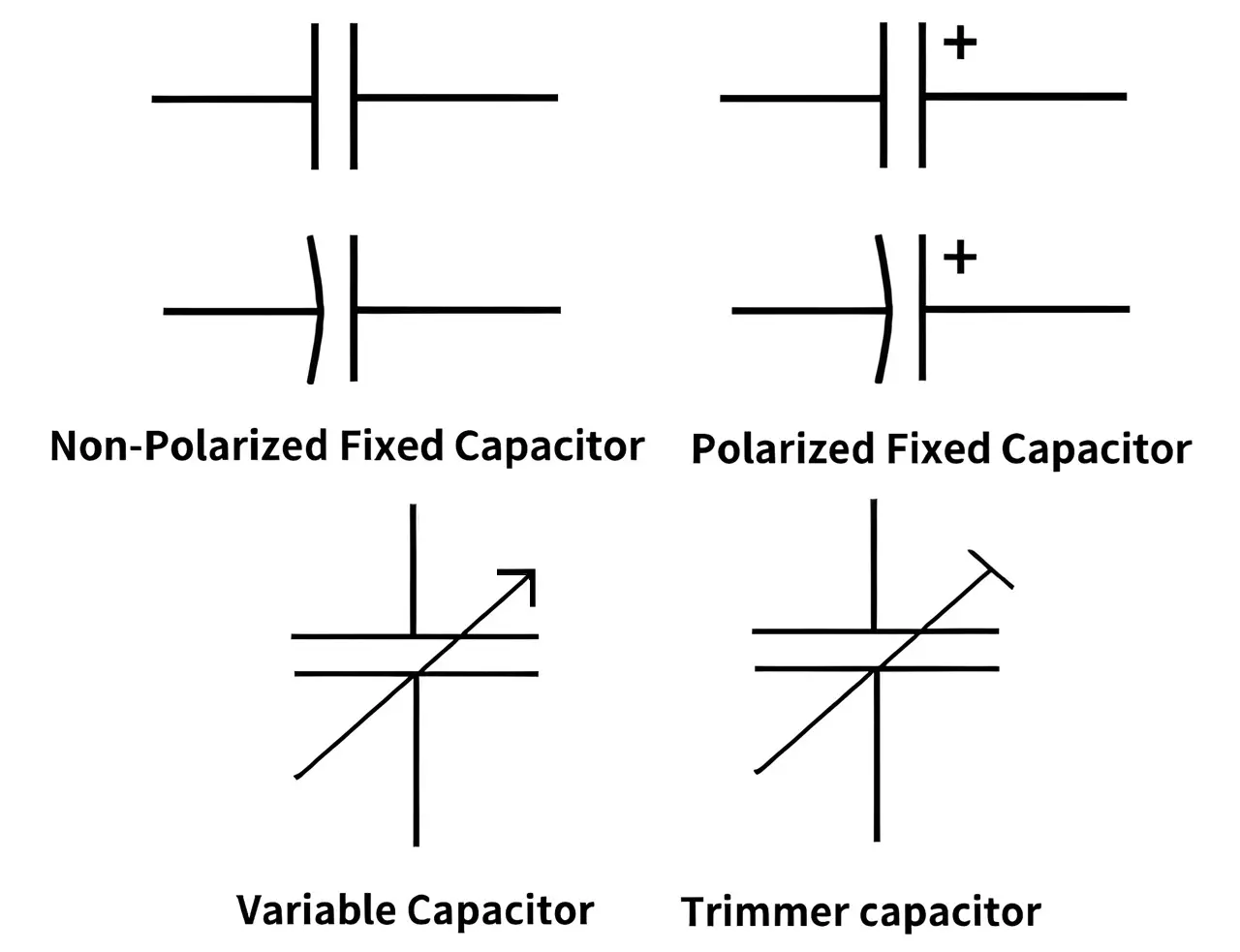
Fixed capacitors have a predetermined capacitance value that does not change during operation. There are Two Types of fixed capacitors non-polarized and polarized.
A. Non-Polarized Capacitors
Non-polarized capacitors can be used in both AC and DC circuits. They are categorized based on their dielectric material:
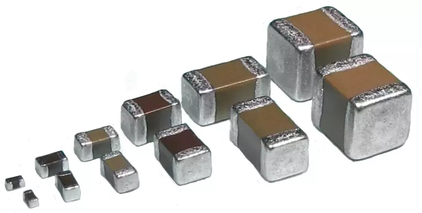
1. Ceramic Capacitors
Ceramic capacitors are widely used electronic components that store electrical charge and are made from ceramic materials as the dielectric. They are known for their stability, reliability, and high-frequency performance.
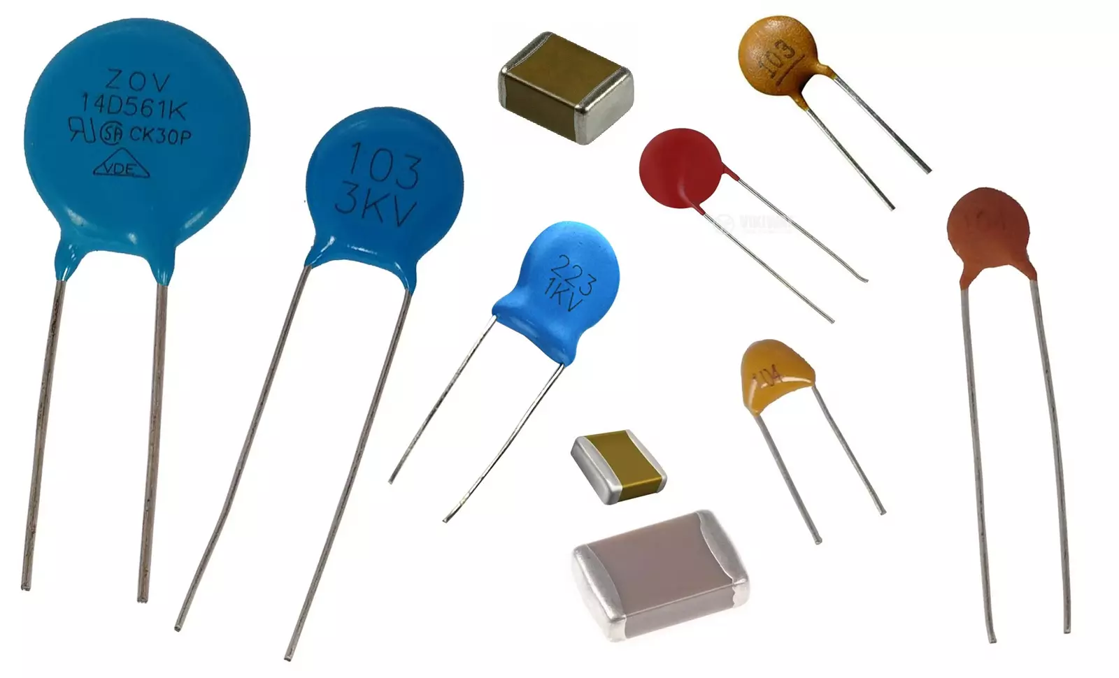
Types of Ceramic Capacitors:
- Multilayer Ceramic Capacitor (MLCC) – Common in surface-mount applications and microelectronics
- Disc Ceramic Capacitors – Used in RF, high-frequency, and high-voltage applications
Advantages of Ceramic Capacitors
Small size – Available in surface-mount (SMD) and through-hole packages
High-frequency performance – Suitable for RF and high-speed applications
Low equivalent series resistance (ESR) – Ideal for filtering and decoupling
Non-polarized – Can be used in AC and DC circuits
Disadvantages
Capacitance variation with temperature and voltage (especially Class 2 capacitors)
Microphonics (Piezoelectric effect) – Can generate noise in sensitive applications
Limited capacitance range – Typically lower capacitance compared to electrolytic capacitors
Applications
Decoupling and bypassing – Used in power supply lines to filter noise
High-frequency circuits – Used in RF and microwave applications
Timing and tuning circuits – Class 1 ceramics provide stable capacitance
LED drivers and power supplies – For smoothing and energy storage
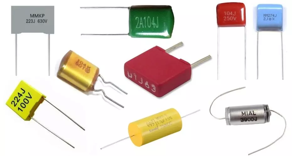
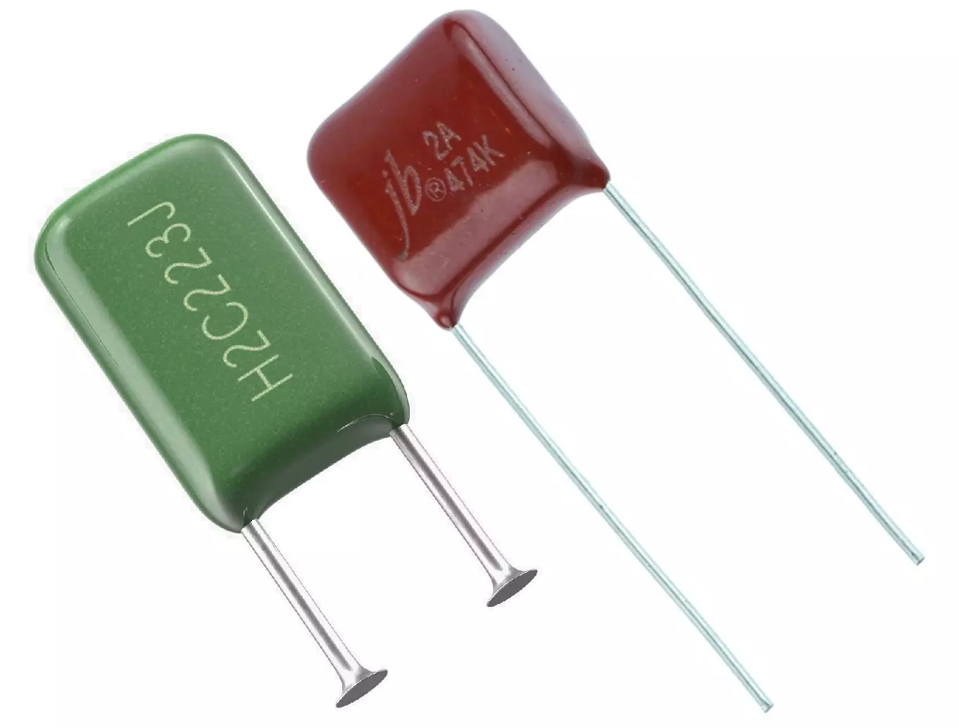
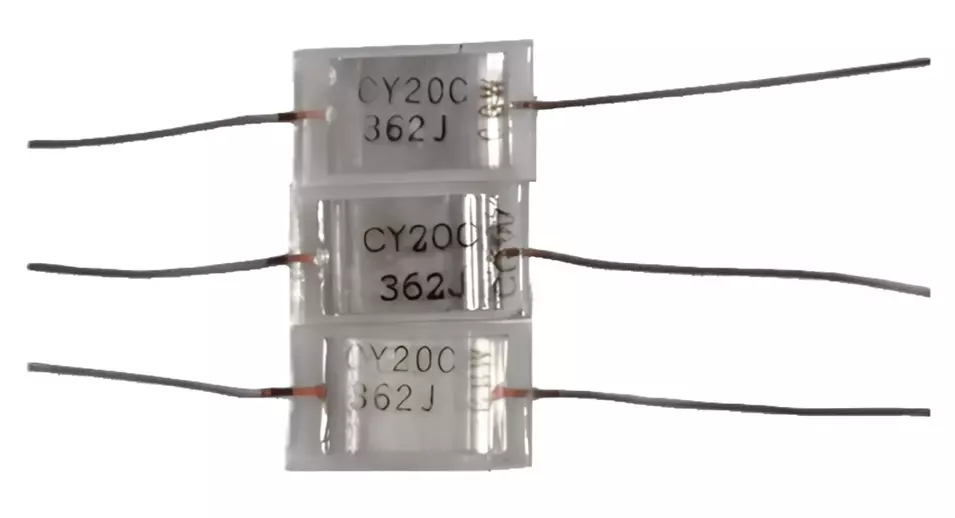
2. Film Capacitors
Film capacitors are a broad category of non-polarized capacitors that use plastic film as the dielectric. They are known for their high reliability, stability, and self-healing properties, making them widely used in power electronics, filtering, snubber circuits, and resonant applications.
Key Characteristics:
Capacitance Range: 100pF to several hundred µF
Voltage Ratings: 50V to 10kV+
Dielectric Materials: Polypropylene (PP), Polyester (PET), Polycarbonate (PC), Polystyrene (PS), etc.
Tolerance: As low as ±1% (high precision)
Temperature Stability: -55°C to +125°C, depending on the type
Non-Polarized: Suitable for AC and DC applications
Self-Healing Property: Extends lifespan in high-voltage applications
Types of Film Capacitors:
- Polyester Capacitors – General-purpose applications, timing circuits
- Polypropylene Capacitors – High-frequency and high-voltage applications, used in power factor correction
- Polystyrene Capacitors – Precision applications due to low tolerance, used in timing circuits
- Polycarbonate Capacitors – Stable over temperature changes, long-term reliability
- Polyphenylene Sulfide (PPS) Capacitors – High stability and reliability, used in automotive and aerospace applications
Advantages of Film Capacitors:
High Stability & Long Lifespan – Low capacitance drift over time
Low ESR & High Ripple Current Handling – Excellent for power electronics
High Voltage Tolerance – Up to 10kV+ for specialized applications
Self-Healing Property – Increases durability in high-stress environments
Non-Polarized – Works in both AC and DC circuits
Limitations:
Larger Size Compared to MLCCs & Electrolytics
Limited Capacitance Density – Not ideal for bulk energy storage
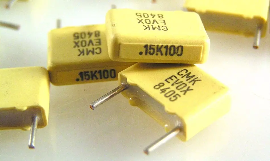
Polyester Capacitors
Polyester capacitors, also called Mylar capacitors, use polyethylene terephthalate (PET) as the dielectric. They are widely used in general-purpose filtering, coupling, and decoupling applications due to their high capacitance density, low cost, and good temperature stability.
Key Characteristics:
Capacitance Range: 100pF to 10µF
Voltage Ratings: 50V to 630V+
Dielectric Material: Polyester (PET) film
Tolerance: Typically, ±5% to ±10%
Temperature Stability: -55°C to +125°C
Non-Polarized: Suitable for both AC and DC circuits
Moderate ESR & Dielectric Absorption: Not ideal for high-frequency precision applications
Advantages:
Compact & High Capacitance Density – Smaller than polypropylene (PP) capacitors
Good Temperature Stability – Works up to 125°C
Non-Polarized & Self-Healing – Durable in DC and AC circuits
Cost-Effective – Cheaper than polypropylene and ceramic capacitors
Decent Frequency Response – Usable in audio and signal processing applications
Limitations:
Higher Dielectric Absorption – Not ideal for precision timing circuits
Higher ESR Compared to PP Capacitors – Less effective in high-frequency applications
Limited Voltage Ratings – Lower than polypropylene (PP) film capacitors
Applications:
- Coupling & Decoupling Circuits – Used in audio and power circuits
- Filtering & Smoothing Applications – Found in DC power supplies
- Pulse & Snubber Circuits – Moderate performance in switching power supplies
- General Signal Processing & Analog Circuits – Used in low-frequency filters
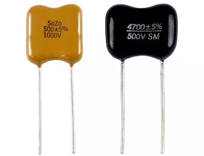
Polypropylene Capacitors
Polypropylene capacitors are film capacitors that use polypropylene plastic as the dielectric. They are widely used in high-voltage, high-frequency, and precision applications due to their low dielectric loss, high stability, and excellent insulation properties.
Key Characteristics:
Capacitance Range: 100pF to several µF
Voltage Ratings: 100V to 3kV+
Dielectric Material: Polypropylene (PP) film
Tolerance: As low as ±1% (very precise)
Temperature Stability: -55°C to +105°C
Non-Polarized: Can be used in both AC and DC circuits
Low ESR & High Q-Factor: Ideal for high-frequency applications
Self-Healing Property: Extends lifespan in high-voltage circuits
Advantages:
Extremely Low Dielectric Losses – Ideal for high-frequency AC circuits
Excellent Stability – Minimal capacitance drift over time and temperature
High Voltage Ratings – Suitable for power electronics, SMPS, and motor applications
Non-Polarized & Self-Healing – Increases durability in high-stress environments
Resistant to Moisture & Aging – Long operational life
Limitations:
Larger Size Compared to MLCCs – Bulkier for the same capacitance value
Lower Capacitance Density Than Electrolytics – Not ideal for bulk energy storage
Applications:
- Switched-Mode Power Supplies (SMPS) – Used in resonant converters, snubber circuits
- Resonant Tank Circuits (LLC Converters, Induction Heating) – High-frequency stability
- DC-Link & Snubber Capacitors – In power inverters and motor drives
- PFC (Power Factor Correction) Circuits – Energy-efficient power management
- Audio Crossovers & High-Fidelity Circuits – High stability and low distortion
- High-Voltage Filtering & Pulse Circuits – Used in Tesla coils, flyback converters
Polystyrene Capacitors
Polystyrene capacitors are film capacitors that use polystyrene plastic as the dielectric. They are known for their exceptional stability, low dielectric absorption, and low loss, making them ideal for precision applications like timing circuits, filters, and analog signal processing.

Key Characteristics:
Capacitance Range: 10pF to 100nF (0.1µF)
Voltage Ratings: 30V to 630V+
Dielectric Material: Polystyrene film
Tolerance: As low as ±1% (high precision)
Temperature Stability: -40°C to +85°C
Low Dielectric Absorption: Excellent for timing circuits
Non-Polarized: Suitable for AC and DC applications
Low ESR & High Q-Factor: Great for RF and audio applications
Advantages:
High Stability & Accuracy – Minimal drift over time
Low Dielectric Absorption – Excellent for precision timing circuits
Very Low ESR & Dissipation Factor – Ideal for high-frequency applications
Non-Polarized & Self-Healing – Can handle AC applications
Limitations:
Limited Capacitance Range – Not suitable for high-energy storage
Low Temperature Tolerance (+85°C Max) – Less robust than polypropylene (PP) capacitors
Fragile & Large in Size – Sensitive to heat, making soldering difficult
Outdated & Hard to Find – Mostly replaced by polypropylene (PP) and C0G (NP0) ceramic capacitors
Applications:
- Precision Timing Circuits – Used in oscillators, clock circuits, and signal processing
- High-Fidelity Audio Filters – Excellent for tone controls, equalizers, and crossovers
- RF & Analog Signal Processing – Used in radio tuners and measurement instruments
- Precision Integrators & Sample-and-Hold Circuits – Due to low dielectric absorption
Polycarbonate Capacitors
Polycarbonate (PC) capacitors are a type of film capacitor that use polycarbonate plastic as the dielectric. They were widely used in the past for their high stability, low dielectric absorption, and excellent temperature tolerance, but they have largely been replaced by polypropylene (PP) and polyester (PET) capacitors due to cost and availability.
Key Characteristics:
Capacitance Range: 100pF to 10µF
Voltage Ratings: 50V to 600V+
Dielectric Material: Polycarbonate film
Tolerance: As low as ±1% (high precision)
Temperature Stability: -55°C to +125°C (better than polyester)
Low Dielectric Absorption: Suitable for precision applications
Non-Polarized: Can be used in both AC and DC circuits
Self-Healing Property: Increases lifespan
Advantages:
High Stability & Low Capacitance Drift – Good for precision circuits
Wide Temperature Range (-55°C to +125°C) – Better than polyester (PET) capacitors
Low Dielectric Absorption – Improves accuracy in timing circuits
Good Frequency Response – Suitable for high-frequency AC applications
Limitations:
Expensive – Higher cost than polypropylene (PP) and polyester (PET) capacitors
Limited Availability – Production has mostly shifted to other film capacitors
Lower Voltage Ratings – Not as robust as polypropylene (PP) capacitors
Applications:
- Precision Timing Circuits – Used in oscillators, timers, and signal processing
- High-Stability Filters – Found in audio and RF applications
- Switched-Mode Power Supplies (SMPS) – Used for snubbers and high-frequency filtering
- Medical & Aerospace Electronics – High reliability under varying conditions
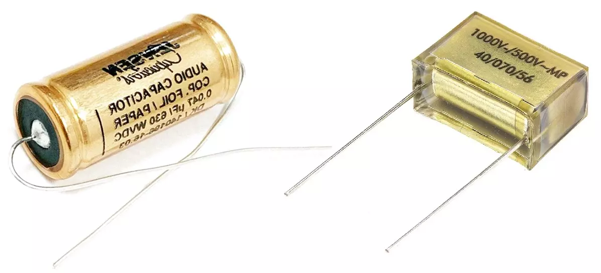
3. Paper Capacitors
Paper capacitors are fixed-value capacitors that use impregnated paper as the dielectric. Though they were widely used in early electrical circuits, they have mostly been replaced by film capacitors due to reliability improvements. However, they are still found in high-voltage and specialized applications.
Key Characteristics:
Capacitance Range: 0.001µF (1nF) to several µF
Voltage Ratings: Up to 2kV or more
Dielectric Material: Waxed, oil-impregnated, or metalized paper
Non-Polarized: Can be used in AC and DC circuits
Good Insulation Resistance but can absorb moisture, leading to degradation
Types of Paper Capacitors:
1. Waxed Paper Capacitors
- Older type, uses wax-impregnated paper
- Prone to degradation due to moisture absorption
2. Oil-Impregnated Paper Capacitors
- More durable, used in high-voltage and power applications
- Found in industrial power factor correction circuits
3. Metalized Paper Capacitors
- Uses a thin metal film on paper dielectric
- Self-healing properties improve lifespan
Advantages:
High Voltage Ratings – Can handle high-voltage applications
Non-Polarized – Works in both AC and DC circuits
Good Stability & Reliability (if well-sealed)
Limitations:
Large Size – Bulkier than modern film capacitors
Moisture Sensitivity – Older waxed types degrade over time
Replaced by Film Capacitors – More efficient alternatives exist
Applications:
- High-Voltage Circuits – Used in older tube amplifiers, rectifiers
- Power Factor Correction – Found in industrial AC circuits
- Snubber Circuits – High-energy pulse applications
- Transformer Protection – Used in some HV isolation designs
4. Glass Capacitors
Glass capacitors are high-performance, highly stable capacitors that use glass as the dielectric. They are known for their extreme reliability, excellent temperature stability, and resistance to environmental factors, making them ideal for high-voltage, RF, aerospace, and military applications.
Key Characteristics:
Capacitance Range: 1pF to 1µF
Voltage Ratings: 50V to 10kV+
Dielectric Material: Glass (fused or metalized)
Tolerance: As low as ±0.1% (very precise)
Temperature Stability: -100°C to +200°C, minimal capacitance drift
Non-Polarized: Can be used in both AC and DC circuits
Low ESR, High Q-Factor: Ideal for high-frequency applications
Moisture & Radiation Resistant: Excellent for harsh environments
Types of Glass Capacitors:
1. Fused Glass Capacitors
- Made by fusing multiple layers of glass
- Extremely stable with low dielectric loss
- Used in high-reliability aerospace and military circuits
2. Metalized Glass Capacitors
- Uses a thin metal layer deposited on glass
- Offers better capacitance density than fused glass types
- Used in precision RF and microwave circuits
Advantages:
Extreme Stability – Minimal capacitance change over time and temperature
Low ESR & High Q-Factor – Excellent for RF and microwave circuits
High Voltage Ratings – Can handle high-voltage pulses
Resistant to Moisture, Corrosion & Radiation – Ideal for space and military use
Long Lifespan – Practically no degradation over decades
Limitations:
Very Expensive – Higher cost than ceramic, film, or mica capacitors
Limited Availability – Produced mainly for aerospace and military applications
Larger Size – Bulkier than equivalent ceramic or film capacitors
Applications:
- High-Frequency Circuits (RF, Microwave) – Used in satellite communications, radar systems
- Aerospace & Military Electronics – Extreme reliability under harsh conditions
- High-Voltage & Pulse Applications – Used in X-ray equipment, power transmission systems
- Precision Instrumentation – Used in high-accuracy measurement circuits
5. Mica Capacitors
Mica capacitors are high-precision, high-stability capacitors that use mica (a natural mineral) as the dielectric. They are known for their excellent electrical properties, high voltage tolerance, and long lifespan, making them ideal for RF circuits, precision timing, and high-voltage applications.
Key Characteristics:
Capacitance Range: 1pF to 10µF
Voltage Ratings: 100V to 10kV+
Dielectric Material: Silver-mica or clamped mica sheets
Tolerance: ±0.1% to ±5% (very precise)
Temperature Stability: -55°C to +125°C, very low temperature coefficient
Non-Polarized: Can be used in both AC and DC circuits
Low ESR & Low Dielectric Losses – Excellent for RF applications
Types of Mica Capacitors:
1. Silver Mica Capacitors
- Uses silver electrodes deposited on mica sheets
- Highly stable and has tight tolerances (±1%)
- Found in precision RF circuits and high-voltage applications
2. Clamped Mica Capacitors (Obsolete)
- Older type, uses clamped mica layers instead of silver
- Less stable than silver mica, mostly replaced by film capacitors
Advantages:
Extremely Stable Capacitance – Minimal drift over time and temperature
Low ESR & High Q-Factor – Ideal for RF and resonant circuits
High Voltage Ratings – Withstands high-voltage and pulse applications
Long Lifespan – Lasts decades with minimal degradation
Limitations:
Expensive – Costlier than ceramic or film capacitors
Large Size – Bigger than ceramic and film capacitors of the same value
Limited Capacitance Range – Not suitable for bulk energy storage
Applications:
- RF & High-Frequency Circuits – Used in radio transmitters, antenna matching networks
- Oscillators & Resonant Circuits – Precision LC circuits and filters
- High-Voltage Applications – Power grid protection, X-ray equipment
- Pulse Circuits & Snubber Networks – Used in HV power supplies
B. Polarized Capacitors
Polarized capacitors must be connected with correct polarity; otherwise, they may be damaged.
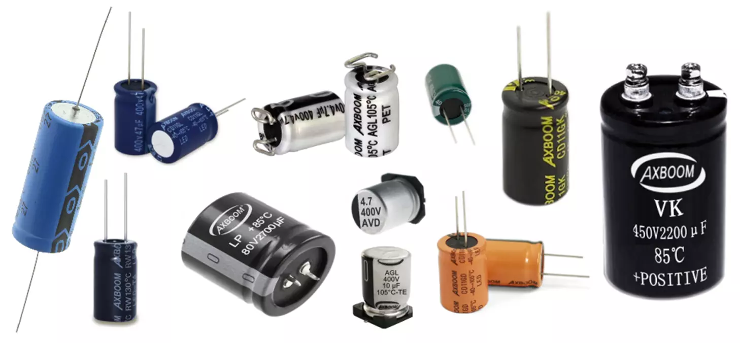
1. Electrolytic Capacitors
Electrolytic capacitors are high-capacitance, polarized capacitors that use an electrolyte to achieve higher capacitance values. They are commonly used in power supplies, filtering, and energy storage applications.
Types of Electrolytic Capacitors:
- Aluminum Electrolytic Capacitors
- Tantalum Electrolytic Capacitors
- Niobium Electrolytic Capacitors
Aluminum Electrolytic Capacitors
Aluminum electrolytic capacitors are widely used for high-capacitance, high-voltage applications. They use an aluminum oxide layer as the dielectric and an electrolyte to achieve high capacitance values.
Key Characteristics:
Capacitance Range: 1µF to several Farads
Voltage Ratings: Typically, 10V to 600V+
Temperature Range: -40°C to +125°C (depending on type)
Tolerance: Typically, ±10% to ±20%
Polarity: Polarized, requiring correct voltage orientation
High ESR (Equivalent Series Resistance): Higher than ceramic or film capacitors
Types of Aluminum Electrolytic Capacitors:
- Standard Aluminum Electrolytic
- General-purpose applications
- Used in power supply filtering and energy storage
- Low-ESR Aluminum Electrolytic
- Designed for switching power supplies (SMPS), DC-DC converters
- Improved ripple current handling
- Solid Polymer Electrolytic
- Uses a conductive polymer instead of liquid electrolyte
- Very low ESR, longer lifespan, and high ripple current capability
- Ideal for high-frequency filtering in power electronics
Advantages:
High Capacitance per Volume – Suitable for power supply filtering
Good Ripple Current Handling – Essential for SMPS and DC-Link applications
Cost-Effective – Lower price compared to film capacitors for high capacitance
Limitations:
Limited Lifespan – Affected by temperature and ripple current (can dry out over time)
Polarity Restriction – Cannot be used in AC applications without special design
High ESR in Standard Types – Can cause heating in high-frequency circuits
Applications:
- Power Supply Filtering – Smoothing DC voltage in rectifiers and SMPS
- DC-Link Capacitors – Energy storage in inverters and converters
- Coupling & Decoupling – Reducing noise in amplifier circuits
- Energy Storage in Pulsed Circuits – Flash circuits, motor drives
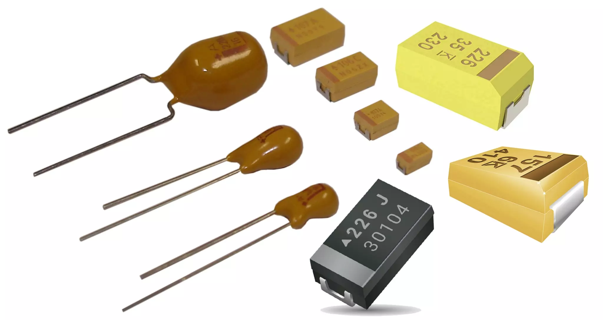
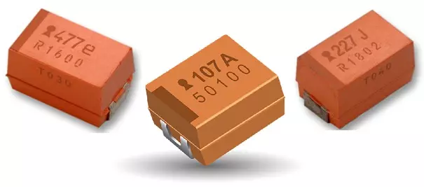
Tantalum Electrolytic Capacitors
Tantalum capacitors are a type of electrolytic capacitor that uses tantalum metal as the anode, with a thin layer of tantalum pentoxide (Ta₂O₅) as the dielectric. They offer high capacitance density, excellent stability, and low ESR, making them ideal for power supply decoupling and filtering applications.
Key Characteristics:
Capacitance Range: 0.1µF to 1000µF
Voltage Ratings: Typically, 2V to 50V, some up to 100V
Temperature Range: -55°C to +125°C
Tolerance: Usually ±5% to ±20%
Polarity: Polarized, requires correct voltage orientation
Low ESR (Compared to Aluminum Electrolytics)
Types of Tantalum Capacitors:
- Manganese Dioxide (MnO₂) Tantalum Capacitors
- Higher reliability, widely used in consumer electronics
- Moderate ESR, used in power rails, filtering, and signal processing
- Polymer Tantalum Capacitors
- Very low ESR, high ripple current capability
- Better thermal stability than MnO₂ types
- Used in high-speed power rails, FPGAs, SMPS, and DC-DC converters
Advantages:
High Capacitance per Volume – Compact size with high energy density
Low ESR & High Ripple Current Capability – Ideal for power applications
Stable Performance Over Temperature & Frequency – More stable than aluminum electrolytic capacitors
Long Lifespan & High Reliability – No drying out, unlike aluminum capacitors
Limitations:
Expensive – Higher cost than aluminum electrolytic capacitors
Voltage Sensitivity – Overvoltage can cause catastrophic failure (short circuit)
Polarity Restriction – Cannot be used in AC applications
Applications:
- Power Supply Decoupling – Stabilizing voltage rails in SMPS and DC-DC converters
- Filtering & Noise Reduction – Used in BMS circuits, microcontroller power supplies
- Medical & Aerospace Electronics – High-reliability applications
- Portable Devices & Consumer Electronics – Smartphones, tablets, SSDs
Niobium Electrolytic Capacitors
Niobium electrolytic capacitors are a safer and more stable alternative to tantalum capacitors. They use niobium oxide (Nb₂O₅) as the dielectric and offer excellent reliability, low leakage current, and better resistance to thermal and electrical stress.
Key Characteristics:
Capacitance Range: 0.47µF to 100µF
Voltage Ratings: Typically, 2.5V to 8V
Temperature Range: -55°C to +125°C
Tolerance: Usually ±10% to ±20%
Polarity: Polarized, requires correct voltage orientation
ESR: Generally higher than polymer tantalum, but lower than aluminum electrolytic
Types of Niobium Capacitors:
- Niobium Oxide (NbO₂) Capacitors
- More stable than tantalum
- Lower risk of short-circuit failure
- Used in low-power circuits, filtering, and decoupling
- Polymer Niobium Capacitors
- Very low ESR, similar to polymer tantalum capacitors
- Better temperature and voltage stability
- Used in switching power supplies (SMPS), DC-DC converters, and high-speed circuits
Advantages:
Safer than Tantalum – Lower risk of thermal runaway or explosion
Good Capacitance Stability – Reliable performance over time
Lower Leakage Current – Ideal for low-power applications
Better Availability & Cost-Effectiveness – Niobium is more abundant than tantalum
Limitations:
Lower Capacitance per Volume than Tantalum – Slightly larger for the same capacitance
Limited Voltage Range – Not available in very high-voltage ratings
Moderate ESR (in NbO₂ types) – Not as low as polymer tantalum
Applications:
- Power Supply Decoupling – Used in SMPS, BMS, and DC-DC converters
- Consumer Electronics – Laptops, smartphones, and SSDs
- Medical & Automotive Electronics – High-reliability circuits
- Battery-Powered Devices – Low-leakage applications
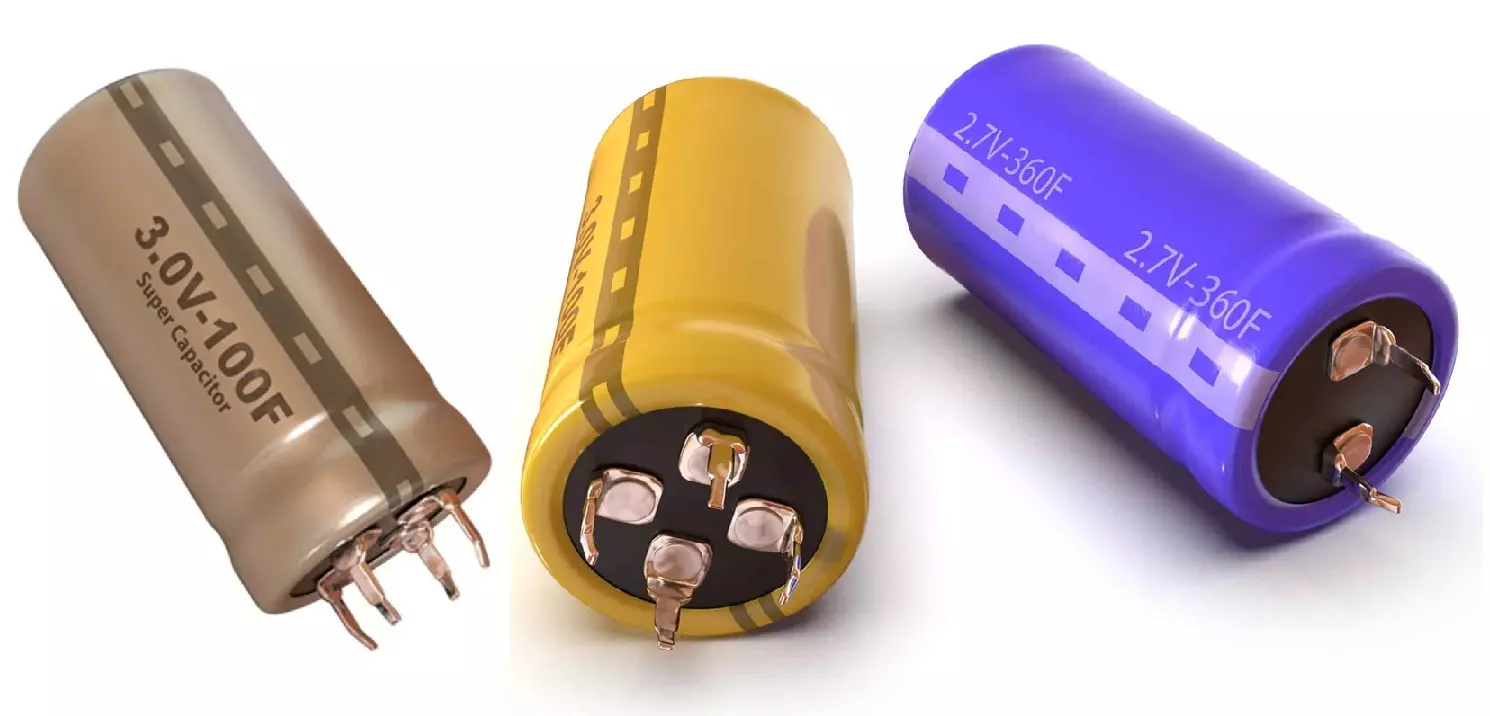
2. Supercapacitors (Ultracapacitors)
Supercapacitors are high-capacity capacitors that store energy through electrostatic charge separation rather than chemical reactions (like batteries). They bridge the gap between regular capacitors and rechargeable batteries by offering high power density, fast charge/discharge, and long cycle life.
Key Characteristics:
Capacitance Range: 0.1F to several thousand Farads
Voltage Ratings: Typically, 2.7V to 3.8V per cell (higher voltages require series configurations)
Temperature Range: -40°C to +85°C (varies by type)
ESR (Equivalent Series Resistance): Low ESR for high-power applications
Charge/Discharge Cycles: 1,000,000+ cycles (compared to ~500-1000 for Li-ion batteries)
Fast Charging & Discharging: Can deliver bursts of power quickly
Polarity: Non-polarized, but should be used correctly in circuits
Types of Supercapacitors:
- Electrochemical Double-Layer Capacitors (EDLCs)
- Most common type
- High capacitance but lower energy density than batteries
- Used for energy storage and backup power
- Pseudocapacitors
- Use fast surface redox reactions for charge storage
- Higher energy density than EDLCs
- Found in hybrid energy storage systems
- Hybrid Supercapacitors
- Combine characteristics of EDLCs and lithium-ion batteries
- Higher energy density than standard supercapacitors
- Used in electric vehicles, regenerative braking, and backup power
Advantages:
High Power Density – Can deliver quick bursts of energy
Long Cycle Life – Over 1 million charge/discharge cycles
Fast Charging – Charges in seconds to minutes
Wide Temperature Range – Suitable for extreme environments
Low Maintenance – No memory effect or degradation like batteries
Limitations:
Low Energy Density – 10-50x lower than Li-ion batteries
Voltage Limitation – Typically 2.7V-3.8V per cell, requiring series balancing circuits
Self-Discharge – Higher than batteries, loses charge over time
Cost – Can be expensive for high-energy applications
Applications:
- Energy Storage & Backup Power – Uninterruptible power supplies (UPS), battery backup
- Regenerative Braking Systems – Captures braking energy in electric vehicles (EVs)
- Peak Power Assistance – Supports power surges in SMPS and DC-DC converters
- Battery Protection – Reduces stress on Li-ion batteries by handling short power bursts
- Solar & Renewable Energy Systems – Energy smoothing and buffering
- IoT & Embedded Systems – Backup power for RTCs and memory retention
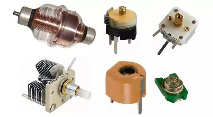
2. Variable Capacitors
Variable capacitors are capacitors whose capacitance can be adjusted mechanically or electronically. They are used in applications that require tunable capacitance, such as radio tuning, impedance matching, and oscillators.
Types of Variable Capacitors:
1. Mechanically Tuned Variable Capacitors
- Air Gap Variable Capacitors
- Uses air as the dielectric
- Low loss, high voltage handling
- Used in radio tuning circuits
- Plastic & Ceramic Dielectric Variable Capacitors
- Higher capacitance in a smaller size
- Used in trimmer capacitors for fine adjustments
- Types:
- Air Dielectric Capacitors – Used in RF circuits, low loss
- Vacuum Capacitors – Used in high-power RF applications, excellent insulation
2. Trimmer Capacitors (Preset Variable Capacitors)
- Small adjustable capacitors for circuit fine-tuning
- Capacitance adjusted with a screwdriver
- Used in RF circuits, oscillators, and sensor calibration
- Types
- Ceramic-based Trimmers – Compact, commonly used in RF applications
- Film-based Trimmers – Stable, used in sensitive circuits
- Mica-based Trimmers – Precision applications, low loss
3. Varactors (Varicap Diodes – Electronically Tuned Capacitors)
- Capacitance changes with applied reverse voltage
- Used in voltage-controlled oscillators (VCOs), RF tuning, and phase-locked loops (PLLs)
- Found in telecommunications, radar, and frequency synthesizers
Key Characteristics:
Capacitance Range: 1pF to 500pF (typical), but can go up to a few nF
Voltage Ratings: Typically 50V to 500V, but can be higher in special cases
Adjustment Mechanism: Mechanical (rotary or sliding) or electronic (varactors)
Temperature Stability: Can vary, depending on the material used
Advantages:
Tunable Capacitance – Allows circuit fine-tuning
Compact & Lightweight – Especially trimmers and varactors
High Q-Factor – For RF and resonant circuits
Electronically Controllable (Varactors) – No mechanical wear
Limitations:
Limited Capacitance Range – Typically low capacitance values
Mechanical Wear (For Rotary Types) – Can degrade over time
Lower Voltage Tolerance (Varactors) – Sensitive to overvoltage
Applications:
- Radio Frequency (RF) Tuning – Used in radio receivers, antenna matching
- Oscillators & Resonant Circuits – Voltage-controlled oscillators (VCOs), LC circuits
- Impedance Matching – For RF amplifiers and antenna circuits
- Sensor Calibration – Fine-tuning capacitance in sensor circuits
3. Special Purpose Capacitors
These capacitors serve specific roles in electrical systems.
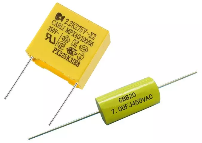
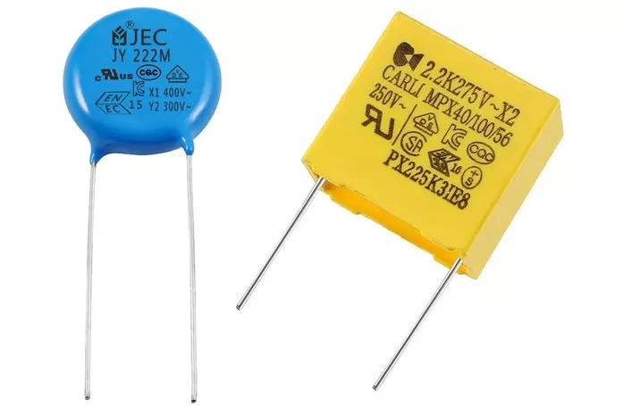
1. Safety Capacitors (X and Y Capacitors)
Safety capacitors are specialized film or ceramic capacitors designed to handle high-voltage transients and EMI filtering in AC mains applications. They prevent electrical shock, interference, and fire hazards, making them essential in switching power supplies (SMPS), chargers, and electrical appliances.
Types of Safety Capacitors
- X Capacitors (Across the Line – Line-to-Line)
- Connected between live (L) and neutral (N) wires in AC circuits
- Used for differential mode noise suppression
- Designed to self-heal and fail open (to prevent fire hazards)
- Types:
- X1 → >2.5kV surge
- X2 → Up to 2.5kV surge (most common)
- X3 → Low voltage, rarely used
- Y Capacitors (Line-to-Ground – Line-to-Earth/Neutral-to-Earth)
- Connected between live/neutral and ground (L-E or N-E)
- Used for common-mode noise suppression
- Designed to fail open or fail short safely (to avoid electric shock)
- Types:
- Y1 → High-voltage applications (>8kV surge, up to 500VAC)
- Y2 → Lower voltage (up to 150-300VAC, ~5kV surge)
- Y3/Y4 → Used in lower-risk applications
Key Characteristics:
Voltage Ratings: 250V to 500V AC (or higher for industrial use)
Dielectric Materials: Polypropylene (PP) film, Ceramic (Class X/Y MLCCs)
Fail-Safe Design: Prevents fire and electric shock
Temperature Stability: -40°C to +125°C
Certified by Safety Standards: UL, IEC, ENEC, CSA, etc.
Advantages:
Prevents EMI (Electromagnetic Interference) in AC power lines
Self-Healing & Fail-Safe Mechanism – Reduces fire risk
Can Handle High Surge Voltages – Protects against power spikes
Essential for SMPS & Power Supplies – Improves safety & reliability
Limitations:
Limited Capacitance Range – Typically 10nF to 1µF
Cannot Be Used for Energy Storage – Strictly for noise suppression & safety
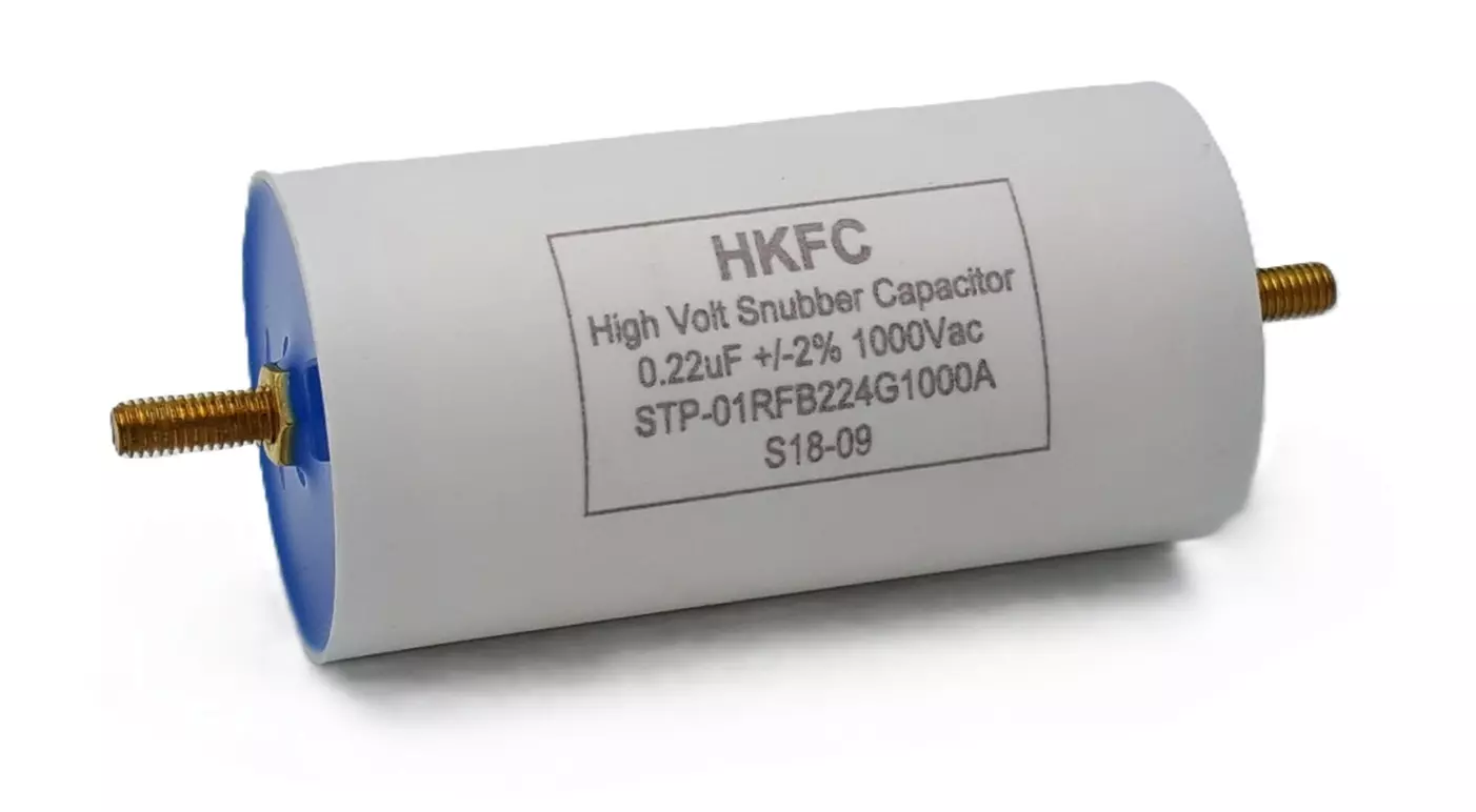
2. Snubber Capacitors
Snubber capacitors are high-frequency, low-ESR capacitors used in power electronics to absorb voltage spikes, suppress oscillations, and protect switching devices like MOSFETs, IGBTs, and thyristors from transient overvoltages. They are critical in switch-mode power supplies (SMPS), LLC resonant converters, and motor drives.
Key Characteristics:
Capacitance Range: 100pF to several µF
Voltage Ratings: 100V to 3kV+
Low Equivalent Series Resistance (ESR) & Equivalent Series Inductance (ESL) → Ensures fast response
High dv/dt Rating → Can withstand rapid voltage changes
High Pulse Current Handling → Protects against switching transients
Non-Polarized → Suitable for AC and DC applications
Types of Snubber Capacitors:
- Film Snubber Capacitors (Polypropylene)
- Ceramic Snubber Capacitors (MLCC, C0G/NP0)
- Mica Snubber Capacitors (Less common today)
Advantages:
Protects Switching Components (MOSFETs, IGBTs, Thyristors) – Reduces stress on semiconductors
Minimizes EMI & Ringing in Switching Circuits – Helps meet EMC compliance
High dv/dt Capability & Fast Response – Handles rapid voltage transients
Prevents Overshoot & Voltage Spikes – Enhances circuit longevity
Reduces Switching Losses – Improves SMPS & inverter efficiency
Limitations:
Requires Precise Selection for Each Application – Incorrect values can increase losses
Limited Energy Storage Capability – Not suitable for bulk capacitance needs
3. Motor-Run & Motor-Start Capacitors
Motor capacitors are used in single-phase AC induction motors to improve starting torque, efficiency, and power factor. They come in two main types:
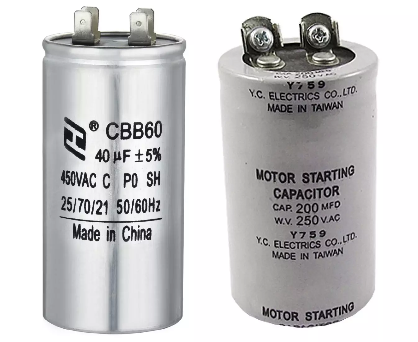
- Motor-Start Capacitors → Provides extra torque during motor startup
- Motor-Run Capacitors → Improves efficiency & performance during continuous operation
1. Motor-Start Capacitors
- Purpose: Used only during motor startup to provide a high starting torque.
- Capacitance Range: 50µF to 600µF
- Voltage Ratings: 110V to 330V AC+
- Dielectric: Electrolytic (Non-Polarized, Oil-Filled or Dry Type)
- Duty Cycle: Short-term use (disconnected after a few seconds by a centrifugal switch or relay).
- Failure Mode: Typically dries out over time or fails open.
- Applications:
Air Conditioners
Compressors
Pumps & Fans
Refrigerators
2. Motor-Run Capacitors
- Purpose: Used continuously while the motor is running to improve power factor & efficiency.
- Capacitance Range: 1µF to 100µF
- Voltage Ratings: 250V to 600V AC+
- Dielectric: Polypropylene Film (Long Lifespan, High Reliability)
- Duty Cycle: Continuous operation
- Failure Mode: Often fails short, causing overheating in motors.
- Applications:
Industrial & Household Fans
HVAC Systems & Blowers
Pumps, Compressors, and Machine Tools
Advantages:
Increases Motor Efficiency & Power Factor – Reduces energy consumption
Provides High Starting Torque – Essential for heavy-load motors
Extends Motor Lifespan – Reduces electrical stress on windings
Polypropylene Film in Run Capacitors – Offers durability and reliability
Limitations:
Motor-Start Capacitors Are Temporary – Must be switched off after startup
Failure Can Cause Motor Overheating or Failure – Run capacitors must be properly rated
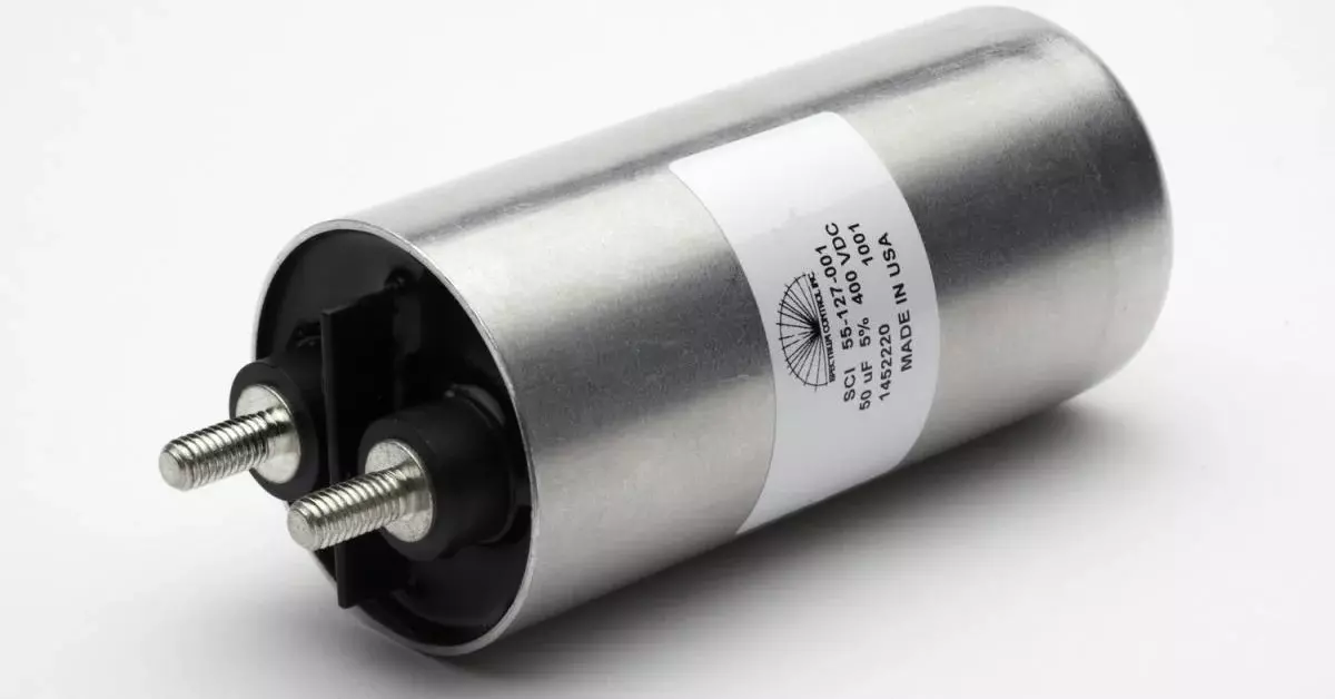
4. Pulse & Power Film Capacitors
Pulse and power film capacitors are designed for high-current, high-voltage, and fast-switching applications where they must handle rapid charge/discharge cycles, high peak currents, and high dv/dt ratings. These capacitors are commonly used in power electronics, pulsed power systems, inverters, and high frequency switching circuits.
Key Characteristics:
Capacitance Range: 100nF to several hundred µF
Voltage Ratings: 100V to 10kV+
Dielectric Materials: Polypropylene (PP), Polyethylene Terephthalate (PET), or Polyphenylene Sulfide (PPS)
High dv/dt Rating: Can withstand rapid voltage changes
Low ESR & ESL: Reduces power dissipation and energy losses
Self-Healing Property: Extends lifespan by recovering from minor breakdowns
Types of Pulse & Power Film Capacitors
- Pulse Film Capacitors (Fast Discharge)
- Power Film Capacitors (Continuous Operation)
- High-Frequency AC Film Capacitors
Advantages:
Handles High Peak Currents – Protects power circuits from surges
Low ESR & ESL – Reduces power dissipation & heating
High Voltage Tolerance – Suitable for 1kV+ applications
Self-Healing Capability – Increases durability & reliability
Excellent Stability – Performs well in high-frequency & resonant circuits
Limitations:
Larger Size Compared to MLCCs & Electrolytics
Higher Cost Than Standard Film Capacitors
5. Radio Frequency (RF) Capacitors
RF capacitors are specialized capacitors designed for high-frequency applications (MHz to GHz range) where low loss, minimal parasitic inductance, and stability are critical. These capacitors are widely used in RF circuits, antenna matching, filters, impedance tuning, oscillators, and RF power amplifiers.
Key Characteristics:
Capacitance Range: 0.1pF to 1000pF+
Voltage Ratings: 50V to 10kV+ (depending on type)
Low Equivalent Series Resistance (ESR) & Low Equivalent Series Inductance (ESL) → Ensures high Q-factor
High Self-Resonant Frequency (SRF) → Operates effectively in RF ranges
Stable Capacitance Over Temperature & Frequency
Materials: Ceramic (C0G/NP0), Mica, Air, Vacuum, or Glass Dielectrics
Types of RF Capacitors
- Ceramic RF Capacitors
- Mica Capacitors
- Vacuum & Gas-Filled RF Capacitors
- Air & Glass Dielectric Capacitors
Advantages:
High Q-Factor & Low Losses – Ideal for RF power circuits
Minimal ESR & ESL – Ensures efficient high-frequency operation
Excellent Thermal & Frequency Stability – Capacitance remains constant
High Self-Resonant Frequency (SRF) – Works well in MHz-GHz applications
Limitations:
Low Capacitance Range – Not suitable for energy storage
Specialized Design Needed for Different RF Bands
6. Coupling, Decoupling & Bypass Capacitors
Coupling, Decoupling and bypass capacitors are used in power supply circuits and signal lines to filter noise, provide stable voltage, and ensure reliable operation of electronic components. While the terms are often used interchangeably, there is a slight distinction:
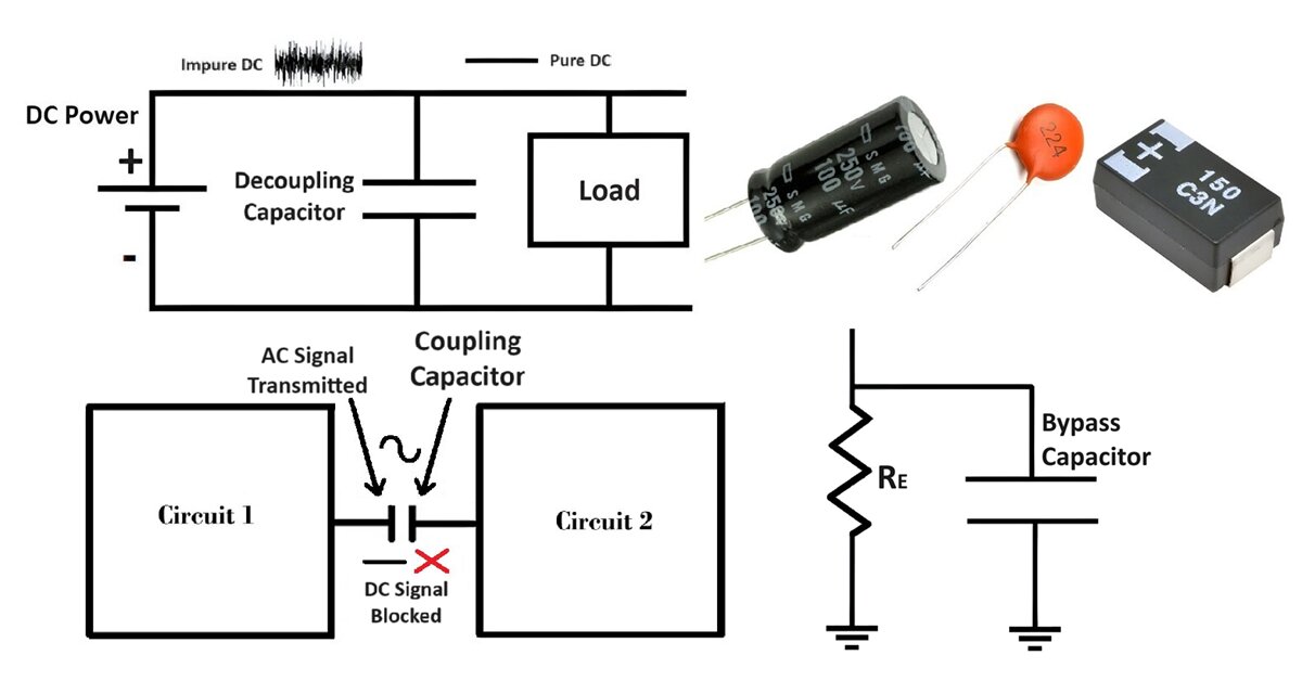
- Bypass Capacitors: Used to shunt AC noise away from sensitive circuit nodes (e.g., from power rails to ground).
- Coupling Capacitor: Provides DC isolation and AC connection.
- Decoupling Capacitors: Provide localized energy storage to stabilize voltage levels and prevent sudden voltage drops.
Key Characteristics:
Capacitance Range: 1pF to 1000µF+
Voltage Ratings: 6.3V to 1000V+
Low Equivalent Series Resistance (ESR) & Low Equivalent Series Inductance (ESL) → Ensures fast response
Dielectric Materials: Ceramic (MLCC), Electrolytic, Tantalum, Film
Placed Close to IC Power Pins for Best Effectiveness
Types
- Ceramic Capacitors
- Tantalum & Electrolytic Capacitors
- Film Capacitors
Advantages:
Reduces Voltage Fluctuations & Noise → Improves circuit reliability
Prevents Ground Bounce & Power Integrity Issues
Limitations:
Capacitor Selection Requires Frequency Consideration – Wrong choice can be ineffective
Ceramic (MLCC) Can Have DC Bias Effect – Reducing capacitance under voltage
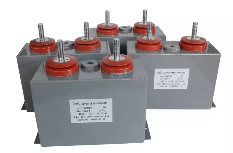
7. Energy Storage Capacitors
Energy storage capacitors are designed to store and deliver large amounts of electrical energy in a short period. They are used in applications where rapid energy discharge, high power handling, and long-term energy retention are required. These capacitors are commonly found in pulse power systems, regenerative braking, UPS systems, medical defibrillators, railguns, and high-power lasers.
Key Characteristics:
Capacitance Range: 100µF to several Farads (F)
Voltage Ratings: 100V to several kV
High Energy Density: Stores large amounts of charge
High Peak Discharge Current Capability
Low ESR & ESL: Ensures efficient energy transfer
Dielectric Materials: Aluminum Electrolytic, Tantalum, Film, Supercapacitors
Types of Energy Storage Capacitors
- Electrolytic Energy Storage Capacitors (Aluminum & Tantalum)
- Film Capacitors (Polypropylene, Polyester)
- Supercapacitors (Ultracapacitors)
- Pulse Power Capacitors
Advantages:
Provides Fast Energy Discharge for High-Power Applications
Reduces Voltage Ripple & Stabilizes Power Supply
Essential for Renewable Energy Systems (Wind, Solar, UPS)
Limitations:
Bulkier Than Batteries for Long-Term Storage
Electrolytic Types Have Limited Lifespan & Higher ESR
Conclusion
Capacitors play a vital role in electronics. Understanding various types of capacitors, their working principles, and applications helps in selecting the best capacitor for a given need. From power electronics to RF circuits, capacitors are integral to modern technology.
Types of Diodes with Symbol, Definition, Working and Applications
