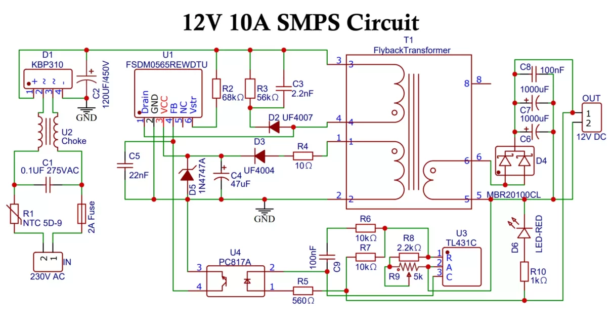
In this article, you will learn to design a 12V power supply circuit. It will convert 230VAC to 12-15V DC, 10A using the FSDM0565RE IC in a flyback configuration. Switch Mode Power Supply (SMPS) circuits are widely used for high-efficiency power conversion. A flyback converter is one of the most popular topologies for low- to medium-power isolated power supplies. The FSDM0565RE is a highly integrated power switch with built-in protection, ideal for compact, cost-effective designs. We will also discuss transformer design and winding calculations to achieve the required output.
1. SMPS Specifications:
Before we dive into the design, let’s summarize the key specifications of our 12V power supply circuit:
- Input Voltage: 230V AC (rectified to ~325V DC)
- Output Voltage: 12V – 15V DC
- Output Current: 10A
- Output Power: Up to 150W (maximum)
- Topology: Flyback
- Controller IC: FSDM0565RE (650V MOSFET included)
- Switching Frequency: ~100 kHz
2. What is Flyback Topology?
In flyback topology, energy is stored in the transformer’s core when the MOSFET is on and transferred to the load when the MOSFET turns off. This topology is ideal for low to medium power levels, offering galvanic isolation and supporting multiple outputs if necessary.
Flyback Converter vs Forward Converter – Detailed Comparison
3. Circuit Components:
- C1 0.1UF 275VAC
- C2 120UF/450V
- C3 2.2nF/1kV
- C4 47uF/50V
- C5 22nF/100V
- C6, C7 1000uF/25V
- C8, C9 100nF
- D1 KBP310
- D2 UF4007
- D3 UF4004
- D4 MBR20100CL
- D5 1N4747A
- D6 LED Red
- F 2A Fuse
- 2 X 5mm 2Pin Screw Terminals
- R1 NTC 5D-9
- R2 68kΩ, 1/4W
- R3 56kΩ, 2W
- R4 10Ω, 1/4W
- R5 560Ω, 1/4W
- R6, R7 10kΩ, 1/4W
- R8 2.2kΩ , 1/4W
- R9 5k Pot
- R10 1kΩ
- T1 Flyback Transformer
- U1 FSDM0565RE IC
- U2 Choke SS11VL
- U3 TL431C
- U4 PC817A
3.1 Input Stage
The input stage converts the 230VAC input to DC using the following components:
- EMI Filter: This filter suppresses electromagnetic interference and typically consists of common-mode chokes and capacitors.
- Bridge Rectifier: Converts AC mains into 325V DC (230V * √2 ≈ 325V). A 1000V, 10A bridge rectifier such as the KBP310 is recommended.
- Bulk Capacitor: A 400V rated electrolytic capacitor is used to smooth the rectified DC. A typical value is 120 – 220µF or more depending on power requirements.
3.2 Flyback Transformer
The flyback transformer is the heart of this design, where voltage conversion and isolation happen. It stores energy when the primary side switch (integrated in the FSDM0565RE) is on and releases it to the secondary when the switch turns off.
The key parameters for the transformer design are:
- Turns Ratio: Determined by the input and output voltage.
- Core Selection: Should be capable of handling the power and frequency.
- Wire Selection: Must be chosen to handle the current while minimizing losses.
We will calculate the required transformer parameters later in this article.
3.3 Secondary Side Components
The secondary side consists of:
- Diode: A Schottky diode or an ultra-fast recovery diode for rectification. For 10A current, the MBR20100 (20A, 100V) is suitable.
- Output Capacitor: Low ESR electrolytic capacitors (e.g., 4700µF, 25V) are used to filter out the ripple from the rectified output voltage.
- LED Light: Power Indicator.
3.4 Control and Feedback
- Optocoupler: Provides isolated feedback to regulate the output voltage.
- Shunt Regulator (TL431): Ensures precise voltage regulation by controlling the feedback signal to the primary-side IC.
3.5 Snubber Circuit
An RCD snubber across the primary winding is necessary to suppress voltage spikes caused by transformer leakage inductance. Typical values are 2.2nF for the capacitor, a diode, and a 56KΩ resistor, but this may vary depending on the design.

4. Transformer Design and Winding Calculations:
The transformer design is critical for efficient power transfer and ensuring the desired output voltage. Here’s a step-by-step guide for calculating the primary-to-secondary turns ratio and selecting an appropriate core.
4.1 Turns Ratio Calculation
To calculate the turns ratio, use the following formula:
Np / Ns = Vin / (Vout + Vd)
Where:
- Np is the number of primary turns.
- Ns is the number of secondary turns.
- Vin is the input voltage to the transformer (325V DC in our case).
- Vout is the desired output voltage (12V-15V DC).
- Vd is the voltage drop across the secondary diode (approximately 0.5V for a Schottky diode).
For an output voltage of 12V:
Np / Ns = 325V / (12V + 0.5V) = 325 / 12.5 ≈ 26
So the primary-to-secondary turns ratio is approximately 26:1.
4.2 Core Selection
The transformer core should be chosen based on the required power and switching frequency. For a 150W output power at 100 kHz, an EE or ETD core with sufficient power handling capacity (e.g., ETD39 or EE35) is recommended. The core material should have low core losses at the chosen switching frequency, such as ferrite (N87, PC44, etc.).
4.3 Number of Primary Turns
The number of primary turns is calculated using the volt-second balance equation:
Np = (Vin × ton) / (Bmax × Ae)
Where:
- Vin is the input voltage (325V).
- ton is the on-time of the switch (calculated based on the duty cycle, typically 50% at maximum load).
- Bmax is the maximum magnetic flux density (e.g., 2000 Gauss or 0.2T for ferrite cores).
- Ae is the effective cross-sectional area of the core.
For a switching frequency of 100 kHz (period = 10µs) and 50% duty cycle, ton is 5µs. Let’s assume Bmax = 0.2T and Ae = 125mm2 for an ETD39 core.
Np = (325V × 5µs) / (0.2T × 125 × 10-6 m2) ≈ 65 turns
4.4 Number of Secondary Turns
Using the turns ratio and the calculated primary turns:
Ns = Np / 26 ≈ 65 / 26 ≈ 2.5 turns
Since fractional turns are not possible, round up to 3 turns for the secondary winding.
5. Thermal Management:
The FSDM0565RE integrates a 650V MOSFET, which can handle the high voltage from the input. However, at higher power levels, heat dissipation can become an issue. A small heatsink may be required for the FSDM0565RE to prevent thermal shutdown.
Additionally, proper PCB layout is critical for minimizing thermal resistance. Use wide copper traces for high current paths and place heat-dissipating components away from sensitive control circuits.
6. Protections:
Include the following protection circuits to enhance reliability:
- Inrush Current Limiter: A Negative Temperature Coefficient (NTC) thermistor to limit inrush current.
- Overvoltage Protection: metal-oxide varistors (MOVs) on the input side to protect against voltage spikes.
- Fuse: A fuse rated for the input current to prevent damage in case of failure.
7. Simulation and Testing:
Before finalizing the design, simulate the circuit using tools like LTspice or PSpice. Verify that:
- The output voltage remains stable under varying load conditions.
- The switching waveform is as expected.
- There is no excessive voltage stress on the MOSFET or diodes.
After building the circuit, testing is essential:
- Measure the output voltage and current.
- Check for excessive temperature rise in the components.
- Ensure the ripple is within acceptable limits.
Applications of 12V SMPS Circuit:
A 12V SMPS (Switched Mode Power Supply) circuit is widely used in various applications due to its efficiency, compactness, and reliability in providing stable 12V DC output from a wide range of input voltages. Here are some common applications of a 12V SMPS circuit:
1. LED Lighting Systems
- Purpose: Powering LED strips, bulbs, and other LED lighting fixtures.
- Why SMPS: Efficient conversion, stable voltage, and reduced heat generation make SMPS ideal for LED drivers, ensuring longer life and consistent brightness of LEDs.
2. Telecommunication Equipment
- Purpose: Powering communication devices such as modems, routers, and telephone systems.
- Why SMPS: The compact and energy-efficient nature of SMPS provides reliable power in telecom applications where stable voltage and low heat dissipation are crucial.
3. Battery Chargers
- Purpose: Charging 12V lead-acid batteries, Li-ion batteries, or other types of rechargeable batteries.
- Why SMPS: SMPS circuits provide precise voltage and current regulation, preventing overcharging and ensuring battery longevity.
4. Embedded Systems
- Purpose: Powering microcontrollers, sensors, and other components in embedded systems.
- Why SMPS: Provides clean and stable power for sensitive electronics, essential for proper functioning of embedded systems and reducing noise.
5. Consumer Electronics
- Purpose: Powering small electronic devices like televisions, DVD players, audio systems, and gaming consoles.
- Why SMPS: The efficiency and ability to handle different input voltages (AC to DC conversion) are key reasons for using 12V SMPS in consumer devices.
6. CCTV Cameras and Security Systems
- Purpose: Providing stable power for CCTV cameras, DVRs, and other security devices.
- Why SMPS: Security systems require continuous operation and stable power, making SMPS circuits ideal due to their reliability and protection against power surges.
7. Automotive Applications
- Purpose: Powering automotive accessories, such as car audio systems, GPS devices, and LED lighting.
- Why SMPS: In cars, where the input voltage may vary widely, a 12V SMPS can provide a stable output, ensuring proper operation of electronic components.
8. Industrial Control Systems
- Purpose: Powering control panels, relays, actuators, sensors, and other industrial automation equipment.
- Why SMPS: Industrial systems often need a reliable 12V DC source for monitoring and controlling processes. SMPS ensures efficient and stable power delivery in harsh environments.
9. Medical Equipment
- Purpose: Powering diagnostic devices, patient monitoring systems, and portable medical equipment.
- Why SMPS: Medical devices require precise, stable, and noise-free power, making 12V SMPS circuits a good fit for sensitive medical applications.
10. Computing and Networking Equipment
- Purpose: Used in power supplies for laptops, desktops, switches, and network routers.
- Why SMPS: These devices require efficient and compact power supplies that can handle a range of input voltages while delivering consistent output.
11. 3D Printers and CNC Machines
- Purpose: Powering motors, control boards, and heating elements in 3D printers and CNC machines.
- Why SMPS: Stable 12V power is necessary for precise operation, and SMPS circuits provide the efficiency and reliability needed for such equipment.
12. Portable Devices
- Purpose: Used in external battery packs, portable amplifiers, and other mobile electronics.
- Why SMPS: Compact design and efficiency make SMPS a suitable power solution for portable devices that need long battery life and stable power.
13. Audio Amplifiers
- Purpose: Powering low- and medium-power audio amplifiers.
- Why SMPS: Audio equipment requires stable and clean power to avoid distortion, which is easily provided by an SMPS circuit.
14. Home Appliances
- Purpose: SMPS circuits are used in low-voltage devices such as cordless phones, clocks, and home automation systems.
- Why SMPS: Energy efficiency and compact design are critical in modern household appliances, and SMPS helps meet those requirements.
15. Robotics and Drones
- Purpose: Powering servo motors, controllers, sensors, and communication systems.
- Why SMPS: Robots and drones need highly efficient power supplies that can deliver stable voltage with minimal weight, making SMPS circuits a key component in these systems.
16. Power Supply for Arduino/Raspberry Pi
- Purpose: Providing power for development boards, such as Arduino and Raspberry Pi.
- Why SMPS: These boards require stable 12V DC power for proper operation and smooth performance in prototyping and IoT applications.
17. Solar Power Systems
- Purpose: Converting the varying voltage from solar panels into a stable 12V DC output for various loads.
- Why SMPS: Efficiency in converting energy from solar sources into usable power is critical for energy-saving applications.
18. Test and Measurement Equipment
- Purpose: Powering oscilloscopes, multimeters, and other testing tools.
- Why SMPS: Precision and stability are essential in test equipment to ensure accurate readings, which are supported by the stable output of SMPS circuits.
In all these applications, the 12V SMPS circuit’s high efficiency, compact form factor, and reliability make it an essential component for delivering stable DC power from AC or varying DC sources.
Conclusion:
Designing an SMPS using the FSDM0565RE IC in a flyback configuration is a cost-effective way to convert 230VAC to 12-15V DC at 10A output. The key challenges in this 12V power supply circuit are selecting the appropriate transformer core and turns ratio, ensuring efficient energy transfer, and providing proper thermal management. By following the guidelines in this article, you can design a robust and efficient power supply.

Hello, Can you help me with what I need to change to get 12V 30 amps from this circuit?
This circuit is not for 30A, you should go for half-bridge or full-bridge SMPS for high power requirements.
HI. I can’t see out what the section or diameter of the wire is on the primary and secondary. Furthermore, on the electrical diagram I see two primaries but you calculate 65 turns for a single primary. So what do we have 65 + 65 turns on the primary? Or what?
thanks for the reply,
Carmine
No it is not a part of primary winding, it is used to power the driver IC at 12V to 18V on VCC pin 3.
How to tune this circuit to work for requirement of Settable voltage of 9 to 18V, and settable current of 5A to 10A
You can use LM5116 or LT3791 IC to make a variable power supply SMPS.
Hi, can you please share the common mode choke current value and inductance ratings.
A 4mH, 5A choke should work well
Hi, Can you please share the alternate part number of this IC FSDM0565REWDTU. Because this IC is not available in the market now.
FSDM0465RE, FSDM07652RE
Hi, Thank you for the reply. But these On semi series IC all are not available in the market now.
Please Check on Amazon
Hello, can we use the flyback topology for a power of 250W ?
Not recommended, consider forward, half-bridge, or LLC topology
and if it’s a 150W switching power supply? Is flyback recommended?
Yes
Hi, Do you have any other circuit for 150W using flyback converter. Because this circuit IC is not available(FSDM0565REWDTU). if any possible to use other company IC for this same circuit.
See this LLC Resonant Converter Circuit
Hi, Thank you for the reply. can you please check this IC (CR6850T) is possible to use in this circuit (12V SMPS).
Yes
Hi, what resistors could i modify around U3 to Have 10V instead of 12V ? regards
Potentiometer R9
Hi, Can you please share the flyback transformer specifications and where that transformers available now.
For specifications see the article, you need to make your own transformer.
Hi, Can you please share the common mode choke Part number.The above mentioned SS11VL part number 4mH and 5A choke not available.
You can get similar one from your local market as well as online.
How can i download the pcb layout to print pcb and please also confirm about the core size because you might have mentioned only ETD35 so just wanted to confirm that its ETD35/42 that has 2 E.
The PCB Gerber file is not made yet, so you will need to design it yourself.
If you do make it, please share it with us by email so others can also use it.
The transformer core size is ETD35/42.
I see two windings on the secondary side yet you calculated for just one!!! what happens to second winding which is believed to be the feedback winding
The Feedback winding should give around 20V at Vcc pin, so calculate according to above formula you will get 5 turns.