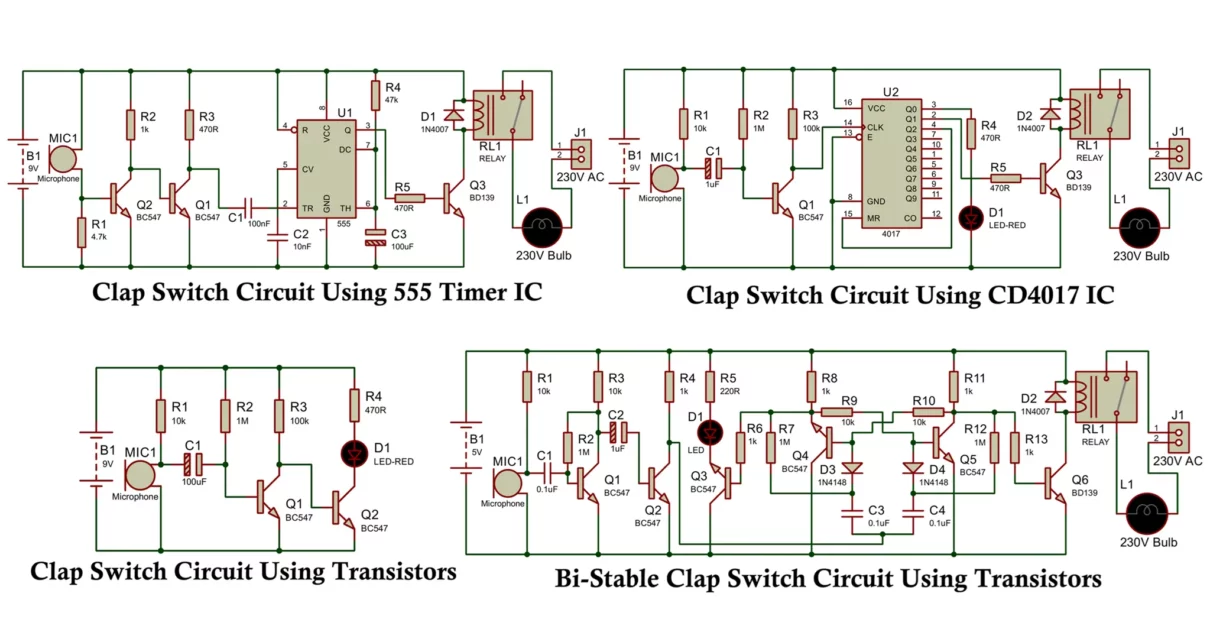
A clap switch circuit is a popular DIY electronics project that lets you control an electronic device by clapping your hands. The circuit uses the sound of a clap as a trigger to turn the device ON or OFF. It finds wide use in home automation, interactive projects, and temporary lighting solutions. In this article, we will explore four simple types of clap switch circuits based on four different designs: using a 555 Timer IC, a 4017 Decade Counter IC, and discrete transistors with capacitors. We will explain their working principles, provide circuit overviews, and discuss their advantages, disadvantages, and applications.
1. Clap Switch Circuit Using 555 Timer IC
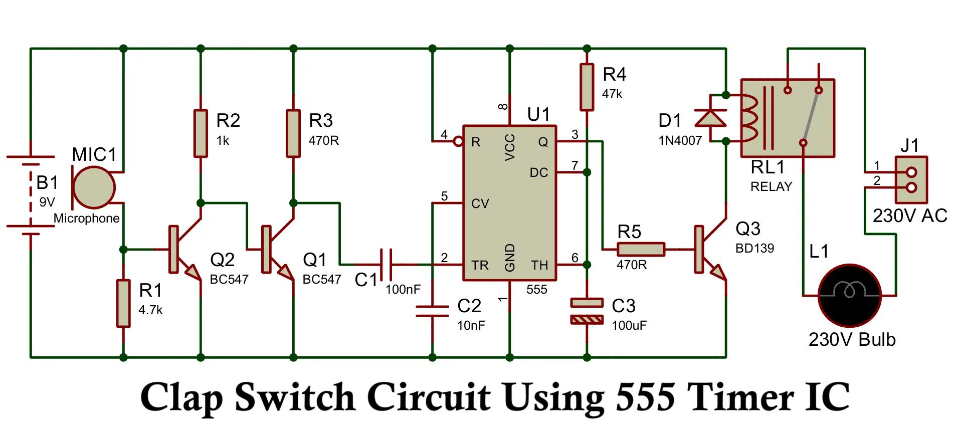
Here is a clap switch having a microphone as input, an amplifier stage of bc547 transistor, a 555 timer to control the LED or relay which can switch ON the appliances for a fixed duration.
Components Required
- Power Supply: B1 – 9V Battery
- Microphone: MIC1 – Microphone
- Resistors: R1 – 4.7 kΩ, R2 – 1 kΩ, R3 – 470 Ω, R4 – 47 kΩ, R5 – 470 Ω
- Capacitors: C1 – 100 nF, C2 – 10 nF, C3 – 100 µF
- Transistors: Q1 – BC547, Q2 – BC547, Q3 – BD139
- IC: U1 – 555 Timer IC
- Diodes: D1 – 1N4007
- Relay: RL1 – Relay
- Output Connector: J1 – Output Connector (230V AC)
- Load: L1 – 230V Bulb
Working of Clap Switch Circuit Using 555 Timer
The clap switch circuit using a 555 Timer IC operates in monostable mode. It detects the sound of a clap through a microphone, amplifies the signal using a transistor, and then triggers the 555 Timer to produce a single output pulse. This pulse can be used to activate a relay or directly drive a device like an LED or a small fan.
- Microphone (Electret Type): Detects the clap sound and converts it into a small electrical signal.
- Amplifier Stage: A transistor (e.g., BC547) amplifies the microphone’s signal to a sufficient level to trigger the 555 Timer.
- 555 Timer IC (Monostable Mode): Configured to produce a single output pulse of a fixed duration when triggered.
- Output Device: The output from the timer can be connected to a relay module or an LED to control devices.
Advantages
- Simple and easy to build.
- Uses readily available components.
- Adjustable pulse duration by selecting resistor and capacitor values.
- Low power consumption.
Disadvantages
- ON time is limited resistor and capacitor values.
- Sensitive to noise; may require fine-tuning to avoid false triggering.
- Not suitable for applications requiring persistent ON/OFF toggling.
Applications
- Temporary light control.
- Basic home automation projects.
- Toy and hobby projects.
2. Clap Switch Circuit Using CD4017 Decade Counter IC
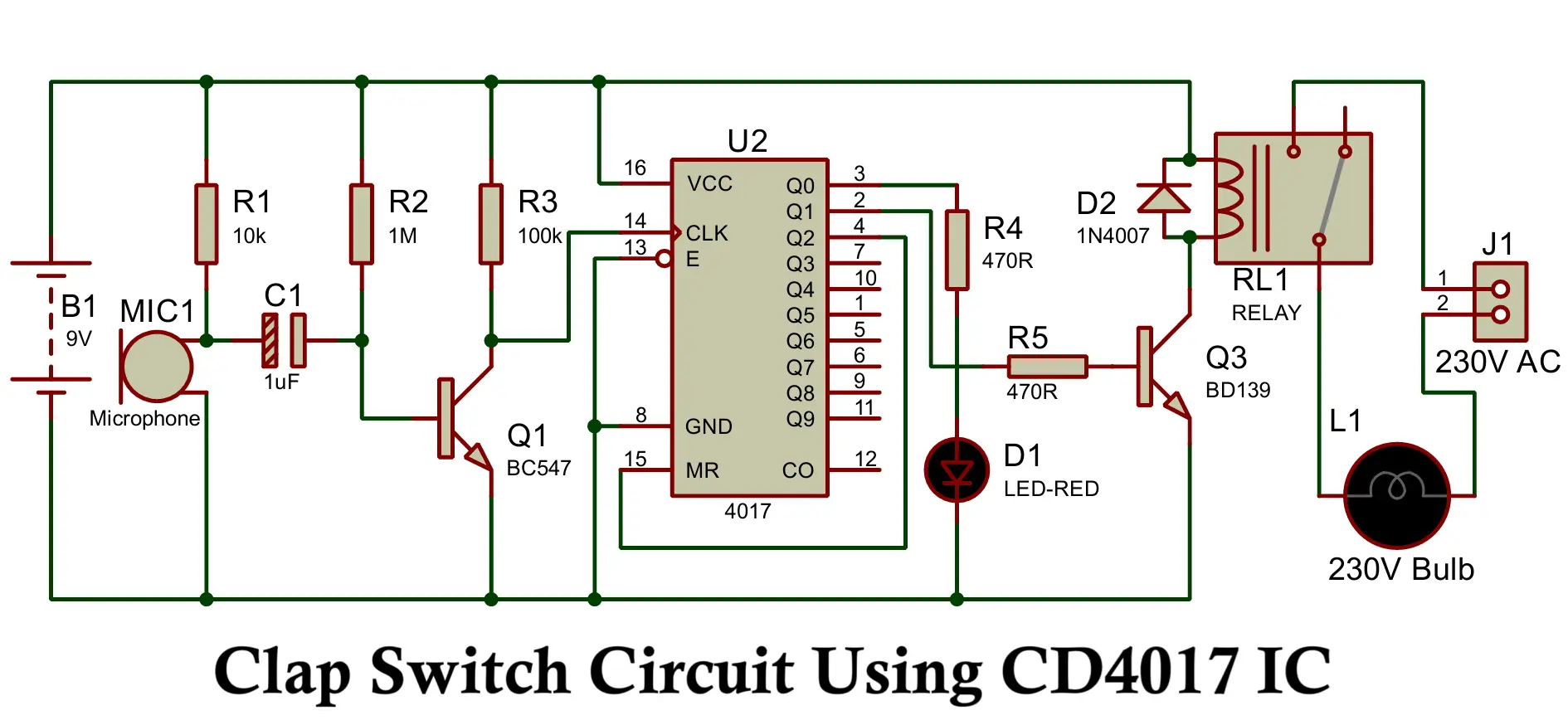
This circuit uses a CD4017 Decade Counter IC along with a microphone and a transistor amplifier. The microphone captures the clap sound and the amplified signal is sent to the clock input of the CD4017. Each clap advances the CD4017 counter, enabling a toggle action between ON and OFF states.
- Microphone and Amplifier Stage: Same as in the 555 Timer circuit, it amplifies the clap signal.
- CD4017 Decade Counter IC: It has 10 output pins and moves to the next output state with every clock pulse received.
- Output Control: The desired output pin (typically Q0 and Q1) is connected to a relay or device to toggle between ON and OFF states.
Components Required
- Power Supply: B1 – 9V Battery
- Microphone: MIC1 – Microphone
- Resistors: R1 – 10 kΩ, R2 – 1 MΩ, R3 – 100 kΩ, R4 – 470 Ω, R5 – 470 Ω
- Capacitor: C1 – 1 µF
- Transistors: Q1 – BC547, Q3 – BD139
- IC: U2 – CD4017 Decade Counter IC
- LED: D1 – LED-RED
- Diode: D2 – 1N4007
- Relay: RL1 – Relay
- Output Connector: J1 – Output Connector (230V AC)
- Load: L1 – 230V Bulb
Working of Clap Switch Circuit using CD4017 IC
This simple yet effective circuit allows you to control electrical appliances like lights, fans, or TVs using sound (specifically, a clap). Let’s break down how each component works together to make this happen.
Sound Detection and Signal Processing
The microphone picks up the sound of a clap and converts it into a weak electrical signal. A 1μF capacitor blocks any DC component, allowing only the AC sound signal to pass to the next stage.
Signal Amplification
The weak signal is amplified by the first BC547 transistor, supported by a 10K and a 1M resistor for proper biasing. A 100K resistor ensures the clock input (pin 14) of the CD4017 IC receives a clean pulse.
Decade Counter Operation
The CD4017 IC has 10 output pins that activate sequentially with each clock pulse. To toggle between ON and OFF with each clap, output pin 2 is connected to the Reset pin (pin 15). This makes the IC cycle between output 1 and 0:
- First clap → output 1 goes HIGH.
- Second clap → resets to output 0.
LED Indicator and Relay Control
A Red LED (with a 470-ohm resistor) is connected to output 0 to indicate the ON state. Simultaneously, a second BC547 transistor connected to output 1 switches the relay, which controls external appliances.
A 1N4007 diode across the relay coil protects the circuit from voltage spikes when the relay switches off.
Power Supply and Control
The circuit is powered by a 9V battery, and you can include a manual ON/OFF switch for power control.
Summary of Operation
- Clap → Microphone picks up sound and converts it to an electrical signal.
- Signal is amplified by the first BC547 transistor.
- Amplified signal triggers the clock input of the CD4017 IC.
- CD4017 cycles between output pins 0 and 1, controlled by resetting after the second clock pulse.
- Output 1 HIGH → Red LED lights up and second BC547 transistor activates the relay.
- Relay switches connected appliances ON or OFF based on the relay state.
This clever design enables simple, hands-free control of various electrical devices with just the sound of a clap.
Advantages
- Provides toggle ON/OFF functionality with each clap.
- Can control multiple devices by utilizing multiple output pins.
- Can be expanded for more complex control schemes.
- More flexible than a 555 Timer monostable design.
Disadvantages
- Slightly more complex circuit design.
- More components involved increase size and assembly complexity.
- More prone to noise and may require debounce circuits or filters.
Applications
- Home automation systems (clap to turn ON/OFF lights or appliances).
- Interactive electronic projects.
- Multiple device control in hobby and educational projects.
3. Clap Switch Circuit Using Transistors
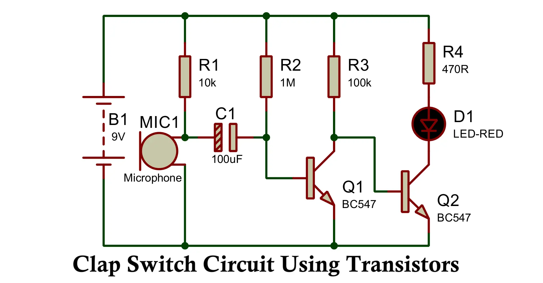
Here is another very simple clap switch circuit having a microphone as input, an amplifier stage of bc547 transistor with 100uF capacitor to control the LED or relay which can switch the appliances ON for a fixed duration.
Components Required
- Power Supply: B1 – 9V Battery
- Microphone: MIC1 – Microphone
- Resistors: R1 – 10 kΩ, R2 – 1 MΩ, R3 – 100 kΩ, R4 – 470 Ω
- Capacitor: C1 – 100 µF
- Transistors: Q1 – BC547, Q2 – BC547
- LED: D1 – LED-RED
Working of Clap Switch Circuit Using Transistors
In this circuit, the microphone and transistor amplify the sound signal, which charges a capacitor. The capacitor holds the charge momentarily and triggers a second transistor that controls the output device. This creates a latching action where the device remains ON for a fixed time, determined by the RC time constant, and then turns OFF automatically.
- Microphone (Electret Type): Detects clap sound.
- Amplifier Stage: A transistor amplifies the signal.
- RC Timing Network: The capacitor and resistor determine the ON duration.
- Transistor Switch: Controls the output device, such as a relay or LED.
Advantages
- Simple and low-cost design with no ICs.
- Easy to build with discrete components.
- Provides latching behavior without additional ICs.
- Low power consumption.
Disadvantages
- Fixed ON duration; not adjustable unless components are changed.
- Cannot toggle between ON and OFF repeatedly; only provides a temporary ON pulse.
- Limited to a single output device.
Applications
- Temporary lighting systems (e.g., auto lamp for a brief period).
- Simple automation where only a single pulse is needed.
- Educational electronics projects.
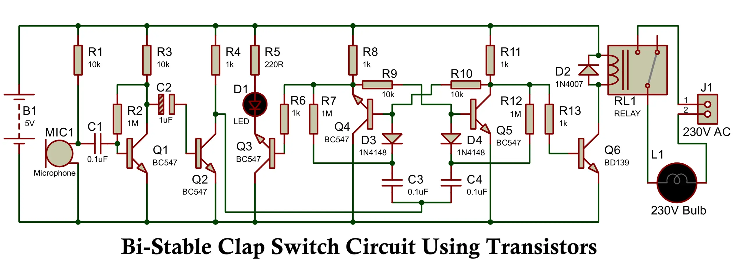
4. Bi-Stable Clap Switch Circuit Using Transistors
This clap switch circuit operates using a bi-stable trigger mechanism combined with an audio frequency signal to control electrical devices. It provides a simple way to turn appliances ON and OFF by detecting sound, such as a clap.
Components Required
- Power Supply: B1 – 5V Battery
- Microphone: MIC1 – Microphone
- Resistors: R1 – 10 kΩ, R2 – 1 MΩ, R3 – 10 kΩ, R4 – 1 kΩ, R5 – 220 Ω, R6 – 1 kΩ, R7 – 1 MΩ, R8 – 1 kΩ, R9 – 10 kΩ, R10 – 10 kΩ, R11 – 1 kΩ, R12 – 1 MΩ, R13 – 1 kΩ
- Capacitors: C1 – 0.1 µF, C2 – 1 µF, C3 – 0.1 µF, C4 – 0.1 µF
- Transistors: Q1 – BC547, Q2 – BC547, Q3 – BC547, Q4 – BC547, Q5 – BC547, Q6 – BD139
- LED: D1 – LED
- Diodes: D2 – 1N4007, D3 – 1N4148, D4 – 1N4148
- Relay: RL1 – Relay
- Output Connector: J1 – Output Connector (230V AC)
- Load: L1 – 230V Bulb
Working of Bi-Stable Clap Switch Circuit Using Transistors
Microphone and Amplifier Stage:
The audio signal received by the microphone (MIC1) is passed through capacitor C1 to the base of transistor Q1. Here, the weak signal from the microphone is amplified. The amplified output from the collector of Q1 is then fed to the base of transistor Q2 for further amplification.
The R1–C1 network acts as a filter so that the circuit is most sensitive to sharp sounds such as claps (typically around a few kilohertz).
Bi-Stable switching stage:
At power ON, the bistable stage formed by Q4 and Q5 is in a defined state: one transistor is ON while the other is OFF. A sudden sound (like a clap) picked up by MIC1 produces a sharp pulse at the collector of Q2. This signal is shaped and passed through the coupling network, then through diodes D3 and D4 connected at the base of Q4 and Q5, which delivers a clean trigger pulse to the bistable circuit for signal conditioning.
- On the first clap, the bistable toggles: Q4 switches OFF, Q5 switches ON. This action also switches ON Q6, which drives the relay coil. At the same time, Q3 (connected to the Q4 side of the bistable) drives the indicator LED D1, showing state of the circuit. The relay now energizes and powers the external load — in this case, a 230 V light bulb connected through connector J1.
- On the next clap, the bistable toggles back: Q4 switches ON, Q5 switches OFF. Now Q6 is turned OFF, de-energizing the relay and disconnecting the 230V load, while the LED driven by Q3 switches accordingly.
Output Control:
Every clap alternately switches the load ON and OFF. The indicator LED confirms the switching action, while the relay safely controls the external 230V AC lamp connected via J1.
Diode D2 is placed across the relay coil as a flyback diode to protect the transistor Q6 from high-voltage spikes generated when the relay is switched OFF.
Safety Note:
Since this circuit directly switches 230 V AC, you must ensure proper insulation, apply relay isolation, and design the PCB and wiring safely to prevent electric shock.
Advantages
- The circuit operates at 5V DC.
- Simple and cost-effective solution for controlling devices without using complex timers.
- Can be used to switch not only LEDs but also other electrical appliances such as fans and tube lights.
- No 555 timer IC is required, simplifying the design.
Disadvantages
- Microphone has a fixed short detection range.
- Prone to false triggers from other loud noises
- Poor sound filtering (not selective)
- No sensitivity adjustment
- Always consumes power
- No delay to prevent multiple triggers from one clap
Applications
This clap switch circuit is versatile and useful in various practical scenarios:
- Automatic switching of LED lights.
- Controlling fans and tube lights with sound.
- Implementing simple sound-controlled home automation systems.
Conclusion
Clap switch circuits are a fun and useful way to implement sound-activated control systems. Depending on your application, you can choose the appropriate circuit design:
This circuit provides a straightforward solution for sound-based control of appliances, combining simplicity with practical utility in home automation.
- The 555 Timer-based circuit is best suited for simple applications where a temporary output is sufficient.
- The CD4017-based circuit is ideal when toggling ON and OFF with each clap is required, especially for home automation and interactive projects.
- The Transistor and Capacitor-based circuit is useful for temporary latching applications where a device should remain ON for a fixed time after a clap.
- The Bi-Stable circuit using Transistor is useful for simple toggle switch applications where a device can be turned ON and OFF by clapping.
By carefully selecting components and optimizing the circuit design, you can build reliable and efficient clap switch circuits for various purposes.
3 Simple IR Proximity Sensor Circuits with Working & Applications
Dual Power Supply Circuit ±(5V, 12V, 15V, 24V & 1.25V-30V DC)
