Let’s understand working of thyristor by construction and explore some of its applications.
Thyristor Definition: Also known as Silicon Controlled Rectifier (SCR), The Thyristor is a three-terminal, four-layer semiconductor device primarily used for high-power control and converting AC current into DC. It is typically used for high-power applications and is capable of switching large amounts of electrical power with very high efficiency. It is composed of silicon materials and is named as such due to its ability to control the flow of current.
Similar to a regular p-n junction diode, Thyristors permits electric current in one direction while blocking it in the opposite direction. However, unlike a diode, which consists of two semiconductor layers (p-type and n-type), the SCR comprises four layers alternating between p-type and n-type materials. Additionally, it features Anode and Cathode terminals, along with a Gate terminal.
The principle of four-layer (P-N-P-N) switching was pioneered by Tanenbaum, Goldey, Moll, and Holonyak of Bell Laboratories in 1956. Thyristor was developed by a team of power engineers led by Gordon Hall. It was commercialized by Frank W. “Bill” Gutzwiller in 1957.
Silicon Controlled Rectifier (SCR) is commonly known as Thyristor, being the most widely used member of the Thyristor family. It finds extensive application in rectification, power regulation, and inversion processes. SCR is an important component in modern switching power supplies and regulating the power flow effectively.
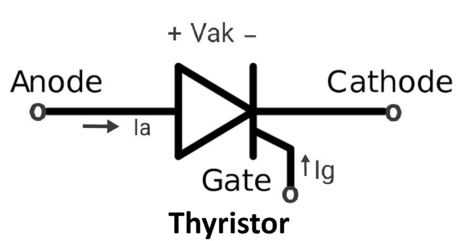
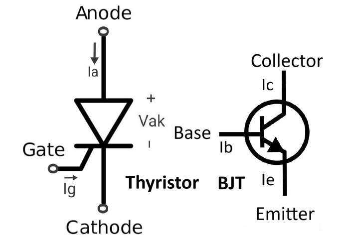
Thyristor Symbol:
Construction of Thyristor:
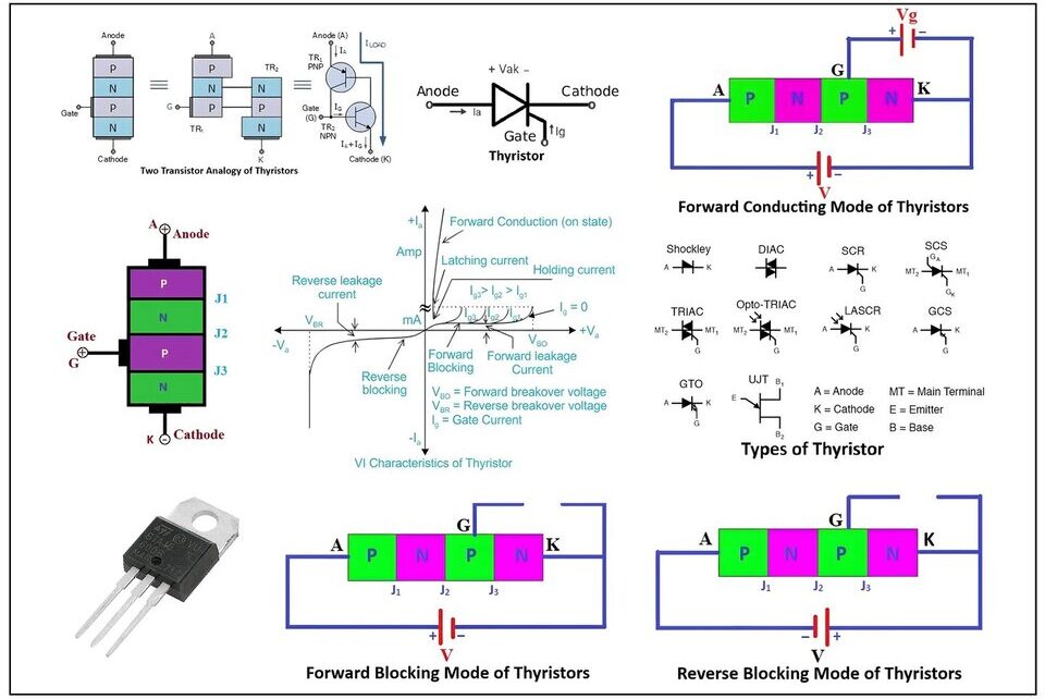
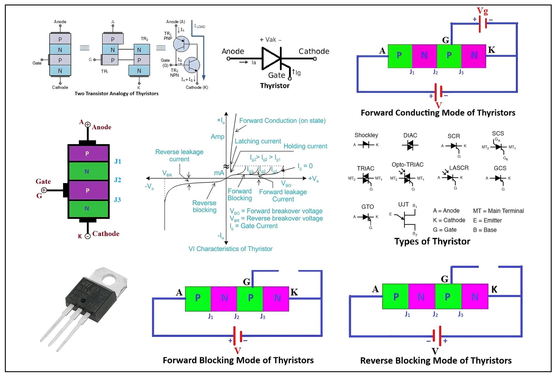
Construction of thyristor and its simplified two-transistor model,
The Silicon Controlled Rectifier (SCR) is a semiconductor device with a four-layer structure consisting of alternating p-type and n-type materials, forming a PNPN or NPNP structure. This arrangement creates three p-n junctions (J1, J2, and J3), which may be alloyed or diffused based on the construction method.
The SCR has three terminals: Anode (A), Cathode (K), and Gate (G). The Gate terminal is connected to the p-type layer nearest to the Cathode terminal in the PNPN structure. The Anode terminal is positively charged and serves as the entry point for conventional current, while the Cathode terminal is negatively charged and acts as the exit point. The Gate terminal controls the flow of current between the Anode and Cathode.
In the PNPN structure, the Anode terminal is connected to the first P-type layer, the Cathode terminal is connected to the last N-type layer, and the Gate terminal is connected to the second p-type layer nearest to the Cathode. The outer layers (first P-type and last N-type) are heavily doped, while the middle P and N-type layers are lightly doped.
- Anode: The top layer of the Thyristor, where the main current enters.
- Cathode: The bottom layer of the Thyristor, where the main current exits.
- Gate: Positioned between the anode and cathode, this terminal controls the Thyristor’s conduction.
- P-N-P-N Layers: The core of the Thyristor consists of four alternating layers of P-type and N-type semiconductor material, forming a P-N-P-N structure.a. P-type Material: It is doped with positively charged carriers (holes).b. N-type Material: It is doped with negatively charged carriers (electrons).
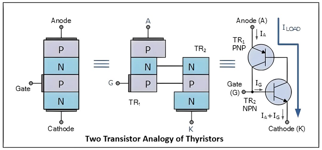
Two Transistor Analogy of Thyristor:
The working of thyristor can be understood as a combination of two-transistors one PNP transistor (Q1) and other NPN transistor (Q2). The emitter of Q1 serves as the Anode terminal, and the emitter of Q2 serves as the Cathode terminal of the SCR. The base of Q1 is connected to the collector of Q2, and the collector of Q1 is connected to the base of Q2. The Gate terminal of the SCR is connected to the base of Q2. This analogy is known as the two-transistor model of the SCR.
Advantages of Two-Transistor Model:
- It simplifies the understanding of Thyristor behavior.
- It provides insight into the self-sustaining nature of Thyristor conduction.
- It aids in analyzing and designing Thyristor-based circuits.
Understanding the construction and working of Thyristors is crucial for their effective utilization in various applications, such as power control and switching circuits.
Thyristor Working Principle:
The working principle of a thyristor involves the control of current flow between its anode and cathode terminals through the application of a gate signal. The key to the thyristor’s operation lies in its ability to latch into the conducting state once triggered, requiring no further gate signal to maintain conduction. This characteristic makes it suitable for applications where a stable, high-power switch is needed.
In summary, the thyristor’s working principle involves the controlled switching between on and off states through the application of a gate signal, allowing the regulation of current flow in high-power circuits.
Modes of operation in Thyristor:
There are three modes of operation in thyristors depending on the voltage bias.
- Forward Blocking Mode (OFF)
- Forward Conducting Mode (ON)
- Reverse Blocking Mode (OFF)
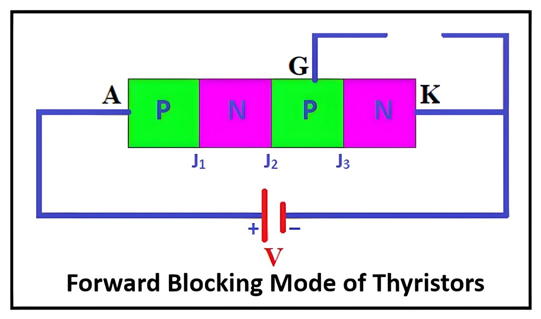
Forward Blocking Mode (OFF):
In this mode, a positive voltage (+) is applied to the Anode (A) terminal, and a negative voltage (-) is applied to the Cathode (K) terminal. The Gate (G) terminal is left open.
Junctions J1 and J3 are forward-biased, while junction J2 is reverse-biased, creating a depletion region that blocks the current flow.
A small leakage current may flow between J2 and J3 due to minority carriers.
When the applied voltage reaches the breakdown voltage, avalanche breakdown occurs, allowing current to flow through the Thyristor. Below the breakdown voltage, the Thyristor remains in the OFF state.
Forward Conducting Mode (ON):
In this mode, Thyristor transitions from the OFF state to the ON state, either by increasing the forward bias voltage beyond the breakdown voltage or by applying a positive pulse to the Gate terminal.
When the forward bias voltage surpasses the breakdown voltage, junction J2 undergoes breakdown, and the Thyristor enters conduction.
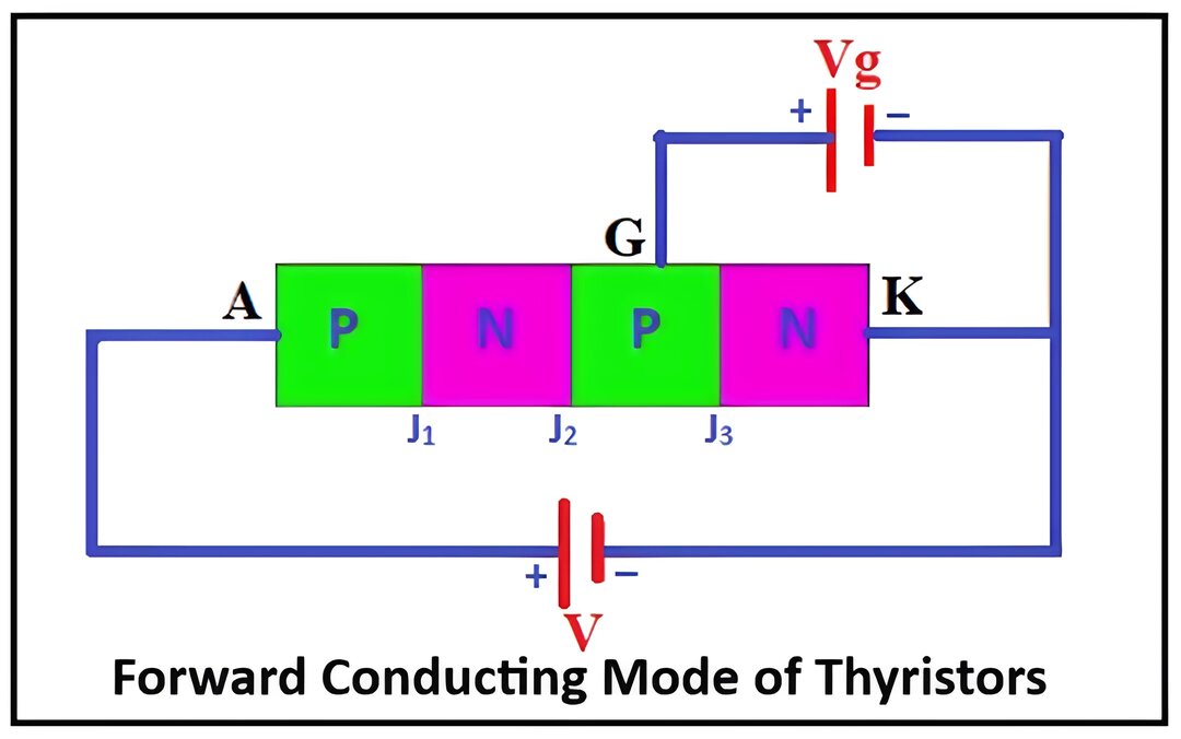
Alternatively, applying a positive pulse to the Gate terminal forward biases J2, allowing current to flow through the Thyristor.
Once conducting, the Thyristor remains in the ON state until the current drops below a certain threshold called the latching current.
Reverse Blocking Mode (OFF):
In this mode, a positive voltage (+) is applied to the Cathode (K) terminal, and a negative voltage (-) is applied to the Anode (A) terminal. The Gate (G) terminal is left open.
Junctions J1 and J3 are reverse-biased, while junction J2 is forward-biased. However, the reverse biasing of J1 and J3 prevents current flow through the Thyristor.
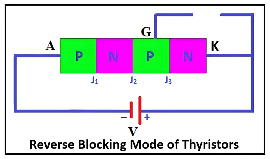
A small leakage current may occur due to carrier drift in J2, but it’s insufficient to turn on the Thyristor.
The Thyristor remains in the OFF state, offering high impedance until the reverse voltage exceeds the reverse breakdown voltage (VBR). If VBR is exceeded, avalanche breakdown occurs at J2, leading to increased reverse current flow, potentially damaging the device due to excessive heat generation.
Understanding these modes of operation is crucial for effectively utilizing Thyristor and SCRs in various applications, ensuring proper switching and control of power flow.
VI Characteristics of Thyristor:
The VI (Voltage-Current) characteristics of a Thyristor provide valuable insights into how it behaves under different operating conditions. Here’s an explanation of the VI characteristics:
Forward Characteristics:
Conduction Region: In the forward bias region, when a positive voltage is applied between the anode and cathode terminals, the Thyristor remains in the off state until the anode voltage (VAK) reaches a certain threshold called the forward breakover voltage (VBO).
Turn-On: Once VAK exceeds VBO, the Thyristor starts conducting. This is called turn-on or firing, and the device enters the conduction state.
Voltage Drop: During conduction, the voltage drop across the Thyristor (VAK) is relatively low and almost constant.
Current Rise: As the Thyristor conducts, the current (IA) rises rapidly, limited mainly by the external circuit resistance.
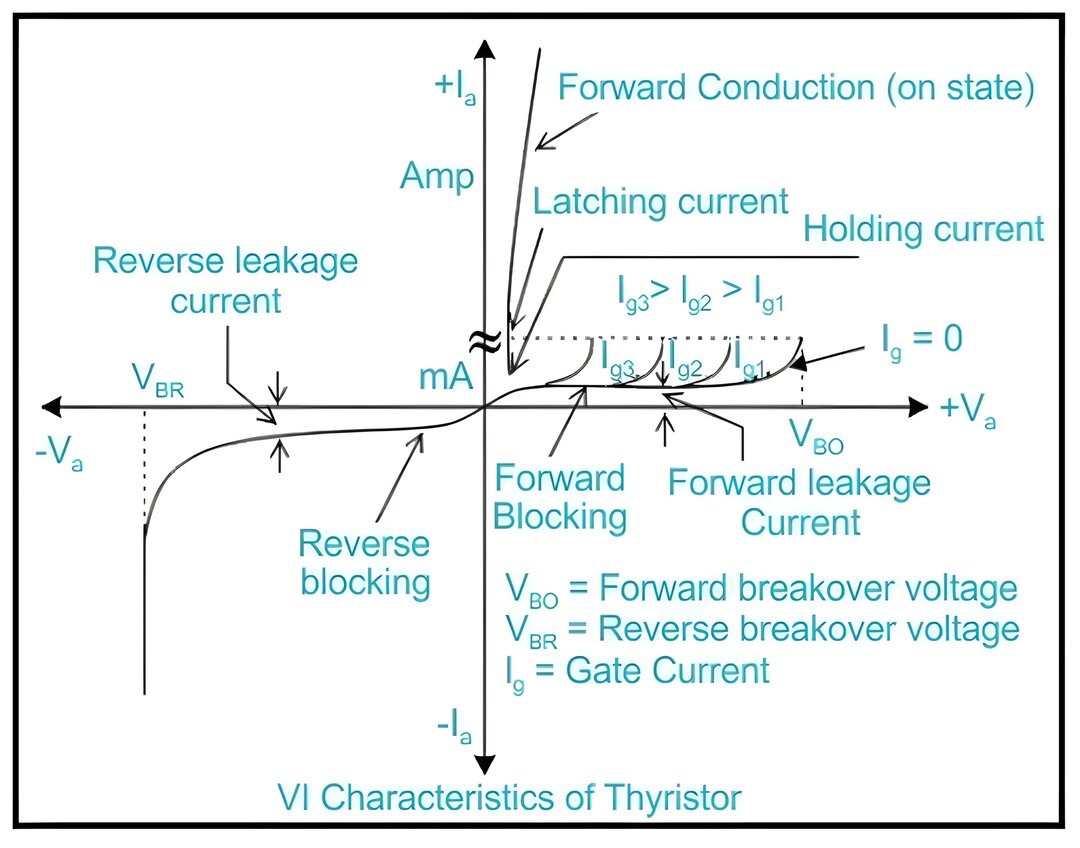
Reverse Characteristics:
Blocking Region: In the reverse bias region, when a negative voltage is applied between the anode and cathode, the Thyristor is in its blocking state, and only a small leakage current flows.
Breakdown: If the reverse voltage (VAK) exceeds the reverse breakdown voltage (VBR), the Thyristor may enter breakdown, allowing a significant reverse current to flow.
Holding Current:
Once turned on, the Thyristor remains conducting until the current through it falls below a certain threshold called the holding current (IH). Below this current, the Thyristor turns off.
Critical Parameters:
Forward Breakover Voltage (VBO): The minimum voltage required to trigger the Thyristor into conduction.
Reverse Breakdown Voltage (VBR): The voltage at which reverse breakdown occurs.
Gate Triggering:
In addition to VAK, Thyristors can also be triggered into conduction by applying a gate signal. The gate current required to trigger the device depends on the device type and its operating conditions.
Understanding the VI characteristics helps in designing and controlling circuits involving Thyristors, ensuring proper turn-on and turn-off behavior for desired applications such as power regulation, switching, and rectification.
Types of Thyristors:
Here are some types of thyristor family devices.
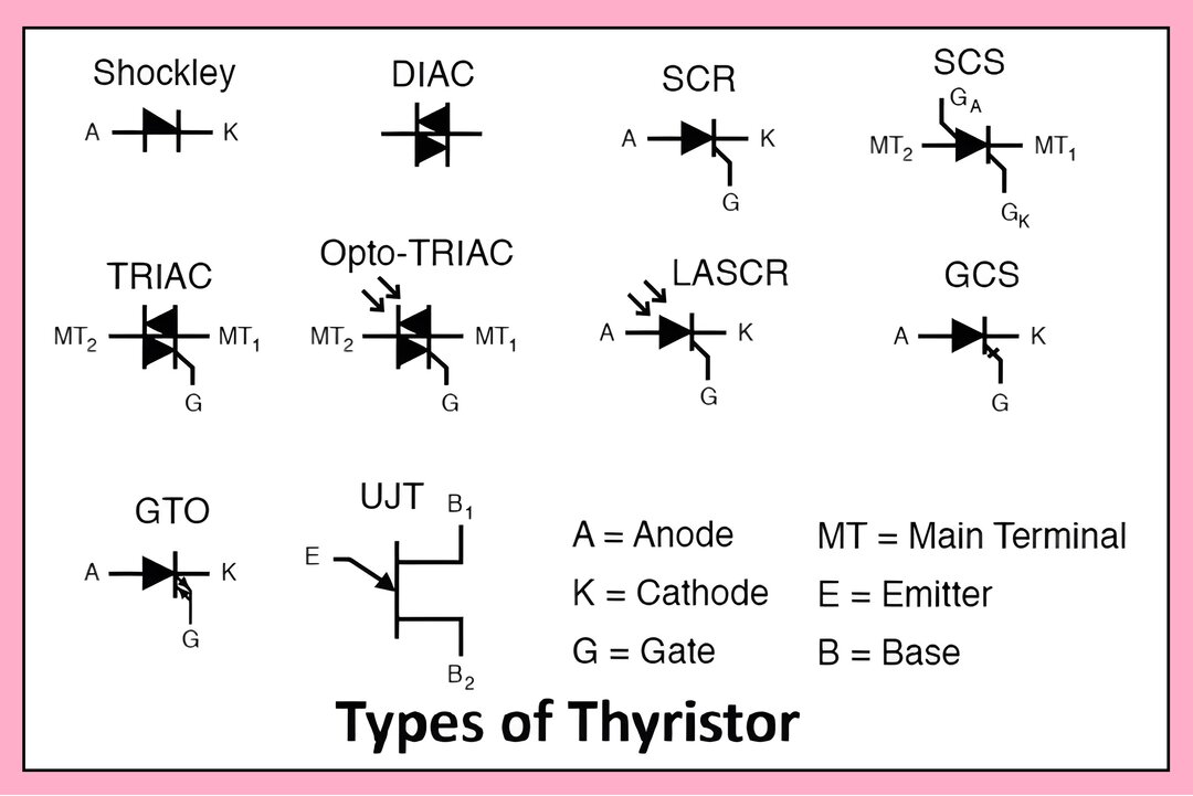
Shockley Diode: The Shockley diode is a four-layer diode, its primary application is to control SCR, which is a bistable switch.
Silicon-Controlled Rectifier (SCR): The most common type of thyristor, used for high-power applications.
Gate Turn-Off Thyristor (GTO): Allows for more control over turn-off operation compared to SCR.
Triode for Alternating Current (TRIAC): A bidirectional thyristor used for AC switching applications.
Diode AC Switch (DIAC): A bidirectional trigger diode used to switch AC voltage.
Silicon-Controlled Switch (SCS): Similar to an SCR but with a gate terminal on both sides.
Light-Activated SCR (LASCR): An SCR that can be triggered by light.
Programmable Unijunction Transistor (PUT): Used for timing and triggering applications.
Static Induction Thyristor (SITh): Used in high-frequency and high-power applications such as RF amplifiers and induction heating.
Reverse Conducting Thyristor (RCT): Combines functions of SCR and diode in a single device. It allows current to flow in both directions and is used in power switching applications.
Bidirectional Triode Thyristor (BTTR): BTTR is a bidirectional thyristor with two gate terminals. It is used in high-power AC applications where bidirectional control is required.
Difference Between Transistor and Thyristor:
| Feature | Thyristor | Transistor |
|---|---|---|
| Structure | Three-terminal, four-layer semiconductor | Three-terminal, three-layer semiconductor |
| Functionality | Unidirectional current control | Bidirectional current amplification and control |
| Current Handling | Typically used for high-power applications | Used for low to medium-power applications |
| Switching Speed | Slower switching speed | Faster switching speed |
| Types | SCR, TRIAC, DIAC, SCS | Bipolar junction transistor (BJT), MOSFET, IGBT |
| Voltage Drop | Higher voltage drop when conducting | Lower voltage drop when conducting |
| Control | Gate signal required to turn on | Base current or voltage required to turn on |
| Applications | Power regulation, rectification, and inversion | Amplification, switching, signal processing |
Protection Of Thyristors:
Advantages of Thyristor:
- High Power Handling: Thyristors can handle high power levels, making them suitable for high-power applications such as motor control, power supplies, and industrial equipment.
- Efficiency: Thyristors have low conduction losses, resulting in high efficiency in power conversion and control applications.
- Fast Switching Speed: Thyristors have fast switching speeds, enabling rapid switching between on and off states in switching circuits.
- Reliability: Thyristors have a rugged construction and can withstand high temperatures and harsh operating conditions, making them reliable for long-term use.
- Low Cost: Thyristors are relatively inexpensive compared to other power electronic devices, making them cost-effective for many applications.
- Simple Control: Thyristors can be easily controlled using simple control signals, such as gate pulses, making them suitable for various control applications.
- Stability: Once triggered into conduction, thyristors remain in the on state until the current drops below a certain threshold, providing stable operation.
- Wide Range of Applications: Thyristors find applications in a wide range of industries, including power electronics, telecommunications, automotive, and aerospace.
Disadvantages of Thyristor:
- Limited Voltage Ratings: Thyristors have limited voltage ratings compared to other power electronic devices such as insulated gate bipolar transistors (IGBTs) and metal-oxide-semiconductor field-effect transistors (MOSFETs).
- Limited Frequency Range: Thyristors are not suitable for high-frequency applications due to their inherent switching characteristics and limitations in turn-off time.
- Unidirectional Conductivity: Thyristors conduct current only in one direction, which limits their use in bidirectional power control applications.
- Gate Signal Required: Thyristors require a gate signal to turn on, which adds complexity to the control circuitry and may introduce additional components.
- Thermal Management: Thyristors generate heat during operation, requiring effective heat sinking and thermal management to prevent overheating and ensure reliability.
- Voltage Drop: Thyristors have a relatively high voltage drop when conducting, leading to power losses in the circuit.
- Limited Overload Capability: Thyristors may be damaged if subjected to high overload currents or voltage spikes beyond their rated specifications.
- EMI Generation: Thyristors can produce electromagnetic interference (EMI) during switching, which may require additional filtering to meet electromagnetic compatibility (EMC) standards.
Despite these disadvantages, thyristors remain widely used in many applications due to their high-power handling, efficiency, and reliability.
SCR as a Switch, its Advantages, Disadvantages and Applications
