Let’s explore JK Flip Flop Truth Table, with its circuit diagram. A flip-flop is a fundamental building block of digital circuits used in digital electronics and sequential logic circuits. It is a type of bistable multivibrator, meaning it has two stable states. Flip-flops are widely used for data storage, data transfer, and control applications in digital systems.
SR flip-flop is the simplest one having two inputs, S (set) and R (reset), and two outputs, Q and Q’. It changes state based on the inputs provided. However, it has a drawback known as the “invalid state” when both inputs are set to 1 simultaneously.
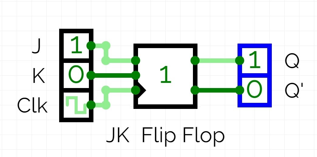
JK Flip-Flop is an enhancement of the SR flip-flop. It has two inputs, J (set) and K (reset), and two outputs, Q and Q’. It eliminates the “invalid state” problem of the SR flip-flop by adding feedback from the outputs.
Logic symbol of the JK flip-flop
The JK flip-flop has some interesting features compared to other flip-flops like the SR (Set-Reset) flip-flop. JK flip-flop is the most widely used universal flip-flop and it can be used in many ways. Here’s the truth table, circuit diagram, and how it works:
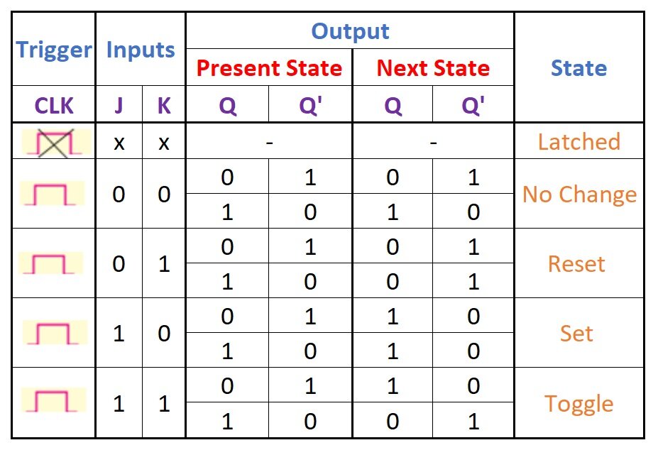
Truth Table of JK Flip Flop:
| J | K | Q(t) | Q(t+1) |
|---|---|---|---|
| 0 | 0 | Q(t) | Q(t) |
| 0 | 1 | Q(t) | 0 |
| 1 | 0 | Q(t) | 1 |
| 1 | 1 | Q(t) | ~Q(t) |
Where:
- Q(t) is the current state of the output.
- Q(t+1) is the next state of the output.
Circuit Diagram of JK Flip Flop:
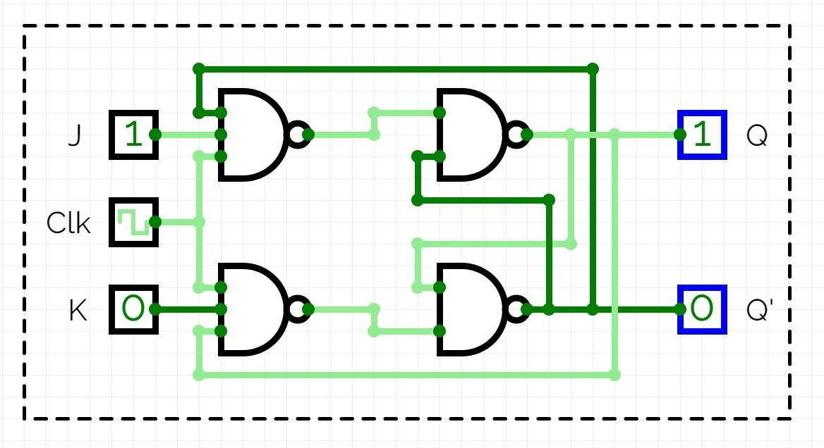
Three input Nand gates have been used in designing of JK flip flop. Nand gate is a universal logic gate.
Working of JK Flip Flop:
- When J=0 and K=0: The output (Q) remains the same as its previous state, maintaining the current state (No change).
- When J=0 and K=1: The output (Q) becomes 0, regardless of its previous state (Reset).
- When J=1 and K=0: The output (Q) becomes 1, regardless of its previous state (Set).
- When J=1 and K=1: The output (Q) toggles to its complement (Complement).
The key feature of the JK flip-flop is its ability to toggle when both J and K are set to 1. This is not present in other types of flip-flops like the SR flip-flop. This makes the JK flip-flop very versatile and useful in various applications including counters, shift registers, and memory storage circuits.
JK Flip Flop Truth Table:
Race Around Scenario in JK Flip-Flop:
The race-around condition happens when both J and K inputs are set to 1 (J = K = 1), and the clock pulse (CLK) remains high for an extended period. In this scenario, the output (Q) starts to toggle continuously between 0 and 1.
Why it Occurs:
- Feedback Loop: JK flip-flops have a feedback path where the output (Q) is connected back to one of the inputs.
- Propagation Delay: Every logic gate has a propagation delay, which is the time it takes for the output to change after an input change.
When J = K = 1, the flip-flop acts like a toggle switch. Here’s how the race unfolds:
- Initially, let’s say Q = 0.
- Due to the high clock pulse (CLK) and J = K = 1, the output (Q) changes to 1 after its propagation delay (Δt).
- But Q’s new value (1) feeds back to the input due to the feedback loop.
- After another propagation delay (Δt), the input change (Q becoming 1) propagates through the flip-flop, causing the output (Q) to switch back to 0.
This continuous back-and-forth change between 0 and 1 due to propagation delays creates an unstable and unpredictable output, hence the term “race-around condition.”
How to Avoid Race-Around Condition:
There are two main ways to eliminate the race-around condition:
-
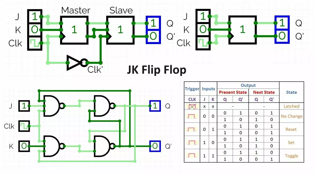
Master-Slave JK Flip-Flop: This is a modified version of the JK flip-flop that uses two cascaded JK flip-flops. One acts as a “master” stage and the other acts as a “slave” stage. It eliminates the timing problems associated with a standard JK flip-flop.
-
Shorter Clock Pulses: Ideally, the clock pulse duration (T) should be significantly shorter than the propagation delay (Δt) of the flip-flop. This minimizes the window for the output change to propagate back and influence the next toggle cycle.
Master-Slave JK Flip-Flop
Standard JK flip-flops can suffer from a phenomenon known as race-around condition. This occurs when the J and K inputs are both set to 1 for an extended period. In this case, the output of the flip-flop oscillates between 0 and 1, making its behavior unpredictable.
Master-Slave JK flip-flops solve this problem by ensuring that the J and K inputs of the flip-flop are only ever seen by the circuitry when the clock signal is high. This prevents the race-around condition from occurring.
How does a Master-Slave JK Flip-Flop work?
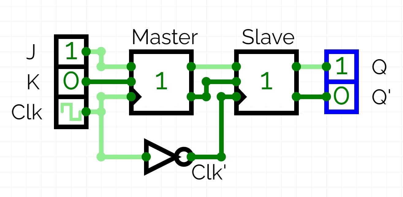
A Master-Slave JK flip-flop consists of two JK flip-flops connected in series. The first flip-flop is the master, and the second flip-flop is the slave. The clock signal is applied to the master flip-flop, and the output of the master flip-flop is fed to the inputs of the slave flip-flop.
- When the clock signal is high, the master flip-flop is active, and the slave flip-flop is inactive. The inputs J and K are sampled by the master flip-flop, and the output of the master flip-flop changes according to the truth table for a JK flip-flop.
- When the clock signal goes low, the master flip-flop becomes inactive, and the slave flip-flop becomes active. The output of the master flip-flop is captured by the slave flip-flop, and the output of the slave flip-flop becomes the new output of the Master-Slave JK flip-flop.
Benefits of Master-Slave JK Flip-Flop
- Eliminates race-around condition.
- Makes the circuit more reliable.
- Can be used in higher-speed applications.
Drawbacks of Master-Slave JK Flip-Flop
- Requires more complex circuitry than a standard JK flip-flop.
- Introduces a slight delay in the output of the flip-flop.
