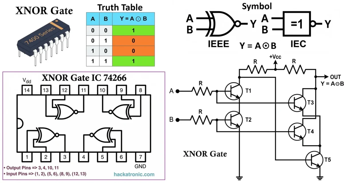
An XNOR Gate (Exclusive NOR Gate) is an important logic gate in digital electronics. It performs a Boolean operation known as equality detection, where the output depends on whether the input values are the same.
In simple terms, an XNOR gate produces an output HIGH (1) only when all the inputs are equal. If the inputs are different, the output becomes LOW (0).
XNOR gates are widely used in digital systems where comparison, verification, and error detection are required. They are essential in applications such as digital comparators, parity generators and checkers, error detection circuits, and data transmission systems.
They are especially important because XNOR logic is used for equality checking, making it a critical building block in digital circuits that require validation and matching operations.
- Related Articles:
- Types of Logic Gates with Symbol, Truth Table and IC Numbers
- Universal NOR Gate Truth Table with IC 7402 PIN Diagram
- NAND Gate Truth Table, Logic Circuit & IC 7400 Pin Diagram
- OR Gate: Symbol, Truth Table, Logic Circuit, and IC Numbers
- AND Gate: Symbol, Truth Table, Logic Circuit, and IC Numbers
- NOT Gate: Symbol, Truth Table, Logic Circuit, and IC Numbers
- XOR Gate: Symbol, Truth Table, Logic Circuit, and IC Numbers
Symbol of XNOR Gate
- Standard Symbol (ANSI)
- The most commonly used XNOR gate symbol (ANSI standard) consists of:
- A shape similar to the XOR gate
- A small bubble (inversion circle) at the output
- Two or more input lines entering from the left
- One output line exiting from the right
- This output bubble indicates the inversion of XOR logic, making it an XNOR gate.
- The most commonly used XNOR gate symbol (ANSI standard) consists of:

- IEC Symbol
- Represented as a rectangle
- Inside marking: =1 with inversion (or sometimes ⊙ depending on notation)
- Inputs enter from the left, output exits from the right
- Multi-Input Symbol
- Additional input lines can be added on the left
- Logic: Output is HIGH if an even number of inputs are HIGH
- Terminal and Notation
- Inputs: A, B, C, D…
- Output: Y or Q
- Boolean expression: Y = A ⊙ B or Y = (A ⊕ B)̅
- The symbol ⊙ represents the XNOR (exclusive NOR) operation
- It can also be written as: Y = AB + A̅B̅
- Important Observations
- Output is HIGH only when inputs are equal
- XNOR is the complement of XOR gate
- Acts as a digital equality detector
- Removing the output bubble → becomes XOR gate
- Used in comparators, parity checking, and error detection systems
Truth Table of XNOR Gate
- Working Principle
- The XNOR gate operates based on an equality condition:
- Output is HIGH (1) when inputs are the same
- Output is LOW (0) when inputs are different
- Unlike the XOR gate, which detects differences, the XNOR gate checks whether the inputs are equal.
- The XNOR gate operates based on an equality condition:
- Boolean Logic
- The XNOR operation follows the Boolean expression: Y = A ⊙ B
- Equivalently, Y = AB + A̅B̅
- This is why it is called an exclusive NOR gate, as it is the complement of the XOR operation.
- The XNOR operation follows the Boolean expression: Y = A ⊙ B

- Key Condition
- Inputs are same → Output = HIGH
- Inputs are different → Output = LOW
- If A = 0 and B = 0 → Y = 1
- If A = 1 and B = 1 → Y = 1
- If A = 0 and B = 1 → Y = 0
- If A = 1 and B = 0 → Y = 0
- This makes the XNOR gate highly useful in equality checking and validation circuits.

- Key Observation
- Output is HIGH if an even number of inputs are HIGH
- Output is LOW if an odd number of inputs are HIGH
- Extended Form: Y = (A ⊙ B ⊙ C ⊙ D …)
- Truth Table Insight
- XNOR gate acts as a digital equality detector
- Used for bit comparison and matching operations
- Important in digital comparators and verification circuits
- Multi-Input XNOR Gates
- Can have more than 2 inputs
- Output depends on parity (even number of HIGH inputs gives HIGH output)
- Widely used in:
- Error detection and correction circuits
- Digital communication systems
- Arithmetic and Logic Units (ALUs)
- Data verification systems
XNOR Logic Circuits
XNOR gate implementation is more complex than AND/OR gates. It requires equality-based conditional logic, not simple conduction
- XNOR is widely implemented using:
- Basic gates (AND-OR-NOT)
- NAND-only logic
- NOR-only logic
- CMOS structures
- XNOR is simply the complement of XOR, so any XOR circuit can be converted into XNOR by adding an inverter stage
Diode XNOR Gate (Diode Transistor Logic)

- Components
- Diodes (D1, D2, D3, D4)
- Transistor (T1)
- Resistors (biasing and pull-up resistor)
- Working
- XNOR gate cannot be implemented using simple diode logic alone because diode logic only supports basic AND and OR operations. To achieve XNOR functionality, a combination of diode logic and transistor inversion is required.
- The circuit is carefully designed such that:
- When both inputs are same (A = B), either both HIGH or both LOW, the diode network prevents a proper conduction path.
- This conduction drives the transistor into OFF state, producing a HIGH output
- When inputs are different (A ≠ B), a valid conduction path is established through specific diode combinations
- As a result, the transistor switches to on state and output becomes LOW
- Key Behavior
- The diode network forms conditional conduction paths
- The transistor stage ensures proper signal amplification and inversion
- Limitation
- Circuit becomes complex due to multiple diode paths
- Voltage drops across diodes reduce output accuracy
- Not suitable for high-speed or precision digital systems
- Mostly of educational and historical importance
Transistor XNOR Gate (RTL / TTL Concept)

- Components
- Transistors (T1, T2, T3, T4, T5)
- Resistors (2kΩ biasing resistors)
- Working Principle
- Transistors operate as electronic switches
- Arranged in both series and parallel configurations to create conditional conduction paths
- Operation
- When A = B (both 0 or both 1): The transistor network keeps the valid conduction path Output node is driven HIGH
- When A ≠ B: Transistor T5 conducts and shorts output to ground via T4 or T3, this prevents output high conduction → output goes LOW
- Key Insight
- Unlike AND/OR gates, XNOR requires condition-based switching
- The circuit must detect equality, not just presence of HIGH signal
- Achieved using carefully arranged switching paths
CMOS XNOR Gate

- Structure
- Built using complementary MOSFETs:
- PMOS (pull-up network)
- NMOS (pull-down network)
- More complex than AND/OR gates because it must detect equality condition
- Built using complementary MOSFETs:
- Configuration
- PMOS network ensures output HIGH when required
- NMOS network ensures output LOW when required
- Both are arranged in complementary symmetry
- Working
- When A = B: Either both PMOS transistors conduct (for LOW inputs) OR both NMOS transistor conduct (for HIGH inputs) → Output becomes HIGH
- When A ≠ B: Alternate path dominates (pull-down) → Output becomes LOW
- Advantages
- Extremely low power consumption
- High noise immunity
- Suitable for VLSI and modern digital IC design
- Most widely used implementation in practical systems
XNOR Using AND, OR, NOT Gates

- Boolean Expression: Y = AB + A̅B̅
- Implementation
- Working
- First term (AB): Output HIGH only when A = 1 and B = 1
- Second term (A̅B̅): Output HIGH only when A = 0 and B = 0
- OR gate combines both outputs
- Final output is HIGH only when inputs are equal
- Key Insight
- XNOR represents two equality conditions combined
- This is the most fundamental and conceptually clear implementation
- Widely used for teaching and logic design analysis
NAND Based XNOR Gate

- Boolean Expression
- XNOR is obtained by inverting XOR (NAND implementation):
- XNOR = NOT (XOR using NAND)
- XNOR function using only NAND gates can be expressed as:
- Y = (A NAND B) NAND((A NAND (A NAND B)) NAND(B NAND (A NAND B)))
- Y = ((AB)′⋅(A(AB)′)′)′⋅((AB)′⋅(B(AB)′)′)′
- This form is derived by systematically replacing AND, OR, and NOT operations with NAND equivalents.
- XNOR is obtained by inverting XOR (NAND implementation):
- Concept
- NAND is a universal gate
- First construct XOR using NAND gates
- Then invert the result using one additional NAND gate
- Working
- Let: D = A NAND B
- E = A NAND D
- F = B NAND D
- XOR Output: X = E NAND F
- Final Output: Y = X NAND X
- Operation Insight
- When A = B: XOR output becomes LOW → inversion makes it HIGH
- When A ≠ B: XOR output HIGH → inversion makes it LOW
- Efficient implementation using only NAND gates
- Very important in TTL logic design
- Common in digital IC internal structures
NOR Based XNOR Gate

- Boolean Expression
- XNOR function using only NOR gates can be expressed as:
- Y = (A NOR (A NOR B)) NOR (B NOR (A NOR B))
- Y = (A NOR (A NOR B)) NOR (B NOR (A NOR B))
- This expression is obtained by converting XNOR into NOR-only logic using De Morgan’s laws and double inversion.
- XNOR function using only NOR gates can be expressed as:
- Concept
- NOR is also a universal gate
- XNOR can be directly realized using NOR structures
- Working
- Let: D = A NOR B
- E = A NOR D
- F = B NOR D
- Output: Y = E NOR F
- Operation Insight
- Intermediate NOR stages generate complemented signals
- Final NOR stage recombines signals to produce equality output
- Often more natural for XNOR implementation than XOR
- Efficient in CMOS technologies where NOR gate is preferred
XNOR IC Numbers and Details
XNOR Gate IC 74LS266
The 74LS266 XNOR Gate IC is a widely used Quad 2-input XNOR gate integrated circuit belonging to the TTL (Transistor-Transistor Logic) family.
It is slightly different from standard ICs because it features open-collector outputs, which require external pull-up resistors.

- Features
- Quad 2-input XNOR gates (4 XNOR gates inside)
- Technology: TTL (BJT-based)
- Open-collector outputs (requires pull-up resistor)
- Propagation delay: ~10–15 ns
- Supply voltage: 5V (fixed)
- Fan-out: Depends on external pull-up configuration
- Pin Configuration
- Total pins: 14
- 4 XNOR gates inside the IC:
- Gate 1: Pins 1, 2 → Output 3
- Gate 2: Pins 5, 6 → Output 4
- Gate 3: Pins 8, 9 → Output 10
- Gate 4: Pins 12, 13 → Output 11
- Power Pins:
- Pin 14: Vcc (+5V)
- Pin 7: GND
Key Characteristic: Each gate operates independently, enabling multiple XNOR operations within a single IC. The open-collector configuration makes it suitable for wired-logic applications and interfacing multiple outputs together.
74HC266 – CMOS XNOR Gate
The 74HC266 XNOR Gate IC belongs to the High-Speed CMOS family.
- Specifications:
- Technology: CMOS
- Supply voltage: 2V to 6V
- Power consumption: Very low
- Propagation delay: ~8–15 ns
- Output type: Open collector (requires pull-up resistor)
Key Characteristic: Combines low power consumption with high-speed switching, suitable for modern digital systems where efficiency is critical.
CD4077 – CMOS Quad XNOR Gate
The CD4077 XNOR Gate IC is part of the 4000-series CMOS family and is one of the most commonly used XNOR ICs.
- Specifications:
- Technology: CMOS (4000 series)
- Supply voltage: 3V to 15V
- Power consumption: Extremely low
- Propagation delay: ~60–200 ns (depends on supply voltage)
- Noise immunity: High
Key Characteristic: Ideal for low-power and battery-operated circuits, especially where speed is not a critical requirement.
74HCT266 – TTL-Compatible CMOS XNOR Gate
The 74HCT266 XNOR Gate IC is designed for compatibility with TTL logic levels.
- Specifications:
- Technology: CMOS with TTL input compatibility
- Supply voltage: Typically, 5V
- Power consumption: Very low
- Propagation delay: Similar to HC series
- Input Levels: LOW ≤ 0.8V, HIGH ≥ 2V
Key Characteristic: Allows direct interfacing between TTL and CMOS circuits without additional level-shifting components.
IC Comparison Table
| IC Number | Technology | Voltage | Speed | Power |
|---|---|---|---|---|
| 74LS266 | TTL | 5V | Medium | Medium |
| 74HC266 | CMOS | 2–6V | High | Very Low |
| 74HCT266 | CMOS + TTL | 5V | High | Low |
| CD4077 | CMOS | 3–15V | Medium | Very Low |
- XNOR ICs are less common than XOR ICs but are crucial for comparison and equality detection circuits
- Open-collector variants (like 74LS266) are useful for wired logic designs
- CMOS versions offer low power and high noise immunity
- Widely used in digital comparators, error detection systems, data verification circuits, communication systems
Timing and Practical Considerations
- Propagation Delay
- Time taken for output to respond to a change in input
- TTL XNOR gates: ~10–15 ns
- CMOS XNOR gates: ~8–15 ns (HC series), higher in 4000 series
- Note: XNOR gates generally have slightly higher propagation delay than simple gates (AND/OR) due to their internal complexity.
- Critical in high-speed digital circuits
- Affects timing in comparators, ALUs, and clocked systems
- Fan-In and Fan-Out
- Fan-In: Number of inputs an XNOR gate can accept
- Typically limited to 2 or 3 inputs in standard ICs
- Fan-Out: Number of logic inputs the output can drive
- TTL: ~10 loads
- CMOS: Higher due to high input impedance
- XNOR gates are less commonly used with very high fan-in due to complexity
- Multi-input XNOR is often implemented using cascaded stages
- Fan-In: Number of inputs an XNOR gate can accept
- Noise Margin
- CMOS > TTL
- CMOS XNOR gates provide better immunity to noise and signal disturbances
- Crucial in communication systems and high-speed digital circuits
- Ensures reliable equality detection
- Power Consumption
- TTL: Higher power consumption
- CMOS: Very low power (µW range)
- CMOS XNOR gates are preferred for:
- Battery-powered devices
- Portable electronics
- Embedded systems
XNOR Logic Example
- Digital Comparator (Equality Detector)
- Consider a system with two inputs:
- Data bit (A)
- Reference bit (B)
- Output (Y) = Equality signal
- If inputs are same → Output HIGH (match detected)
- If inputs are different → Output LOW
- Consider a system with two inputs:
| A | B | Y |
|---|---|---|
| 0 | 0 | 1 |
| 0 | 1 | 0 |
| 1 | 0 | 0 |
| 1 | 1 | 1 |
- XNOR acts as a digital equality detector, widely used in comparison circuits / binary comparator / bit matching.
- Essential in multi-bit comparators
- Forms the basis of equality checking in digital systems
XNOR Logic Circuit Implementations
- Using Switches (Mechanical Logic)
- Requires combination of switches (series + parallel)
- Designed to allow current only when inputs are equal
- More complex than OR/AND logic
- Rarely used in simple mechanical systems
- Using Relay Logic
- Combination of relay contacts arranged to detect equal inputs
- Output energizes only for XNOR condition
- Used in specialized industrial logic systems
- Using FPGA / Digital Systems
- Implemented using HDL: assign Y = ~(A ^ B);
- Used in FPGA design, ASIC circuits, and microprocessor logic
Applications
- In Digital Electronics
- Digital comparators
- Equality detectors
- Parity checkers (even parity systems)
- Error detection circuits
- In Computing Systems
- Arithmetic Logic Units (ALUs)
- Data comparison operations
- Error detection and correction
- Bit matching operations
- In Communication Systems
- Data verification
- Error detection (even parity checking)
- Encoding and decoding systems
- In Everyday Electronics
- Microcontrollers
- Embedded systems
- Digital testing equipment
- Signal validation circuits
Advantages
- Excellent for equality detection
- Essential in comparison circuits
- High noise immunity (especially CMOS)
- Widely used in verification and validation systems
- Flexible in logic design
Limitations
- More complex than basic gates (AND, OR)
- Slightly higher propagation delay
- Requires multiple gates for implementation
- Not commonly used as a standalone universal logic element
XNOR Gate vs AND Gate vs OR Gate vs NOT Gate
| Feature | XNOR Gate | OR Gate | AND Gate | NOT Gate |
|---|---|---|---|---|
| Boolean Expression | A ⊙ B | A + B | A · B | A̅ |
| Output Condition | Inputs same | Any input HIGH | All inputs HIGH | Inverts input |
| Output Behavior | Equality-based | Flexible | Strict | Opposite |
- Key Differences:
- XNOR Gate: Output HIGH only when inputs are same
- OR Gate: Output HIGH if any input is HIGH
- AND Gate: Output HIGH only if all inputs are HIGH
- NOT Gate: Reverses input logic
Conclusion
The XNOR gate is a fundamental and highly important logic gate in digital electronics that performs equality-based logic operations. It outputs HIGH only when inputs are the same, making it essential for comparison, verification, and error detection systems.
Key Insights
- XNOR gate is an equality detector and comparator
- Core component in:
- Digital comparators
- Error detection systems
- Data verification circuits
- Truth table defines equality logic behavior
- Implemented using:
- Basic gates (AND-OR-NOT)
- NAND/NOR logic
- CMOS technology
- Available in various IC families:
- 74LS266, 74HC266, 74HCT266, CD4077
From equality checking in digital systems to error detection in communication circuits, XNOR gates play a critical role in modern electronics. Understanding their working, implementation, and applications is essential for mastering both fundamental and advanced digital logic design.
Types of Logic Gates with Symbol, Truth Table and IC Numbers
XOR Gate: Symbol, Truth Table, Logic Circuit, and IC Numbers
AND Gate: Symbol, Truth Table, Logic Circuit, and IC Numbers
NOT Gate (Inverter): Symbol, Truth Table, Logic Circuit, and IC Numbers
Classification of Digital Logic Families with Characteristics and Applications
