In the world of digital electronics, Karnaugh Mapping (K-map) plays an exclusive role in analyzing and simplifying logic expressions. Digital electronics deals with discrete-valued digital signals and the electronic system is based on the logical uses of the binary notations (0 & 1) to represent the states of the variable involved in the circuit.
In the circuit, the binary digit “0” represents the state of the switch being off (also shows a false state of the statement in logic gates) and the digit “1” represents that the switch is on (the statement is true in a logical expression). Thus, Boolean expression simplification plays an important role in the design of the circuit and the analysis of digital electronic systems.
To achieve this objective use the Boolean algebraic laws and DeMorgan’s theorem. These laws and theorems help us to solve logical expressions, But this process is very long and there are chances of error as the number of variables increases.
For this, there is a need for a new technique like the karnaugh-map to solve logical expressions. In this guide, you learn the full details about K-map and how to implement it to solve the logic.
What is the Karnaugh Map?
A Karnaugh map is a graphical representation of a truth table, organized in a grid where each cell represents a unique combination of input variables. The map allows circuit designers to identify and group adjacent cells (minterms) that share common variables and helps us to reduce the complexity of the Boolean function.
It was introduced by Maurice Karnaugh in 1953. K-map is also referred to as the 2D-Truth table.
The K-map converts values into cells within a rectangular or square grid following a specific pattern. The number of cells in the K-map corresponds to the number of input variables and is calculated as , where is the number of input variables.
For example: to simplify the logic of the two inputs we require the k-map with the 4-cells (22=4). For a four-input logical expression, we need the 16-cell.

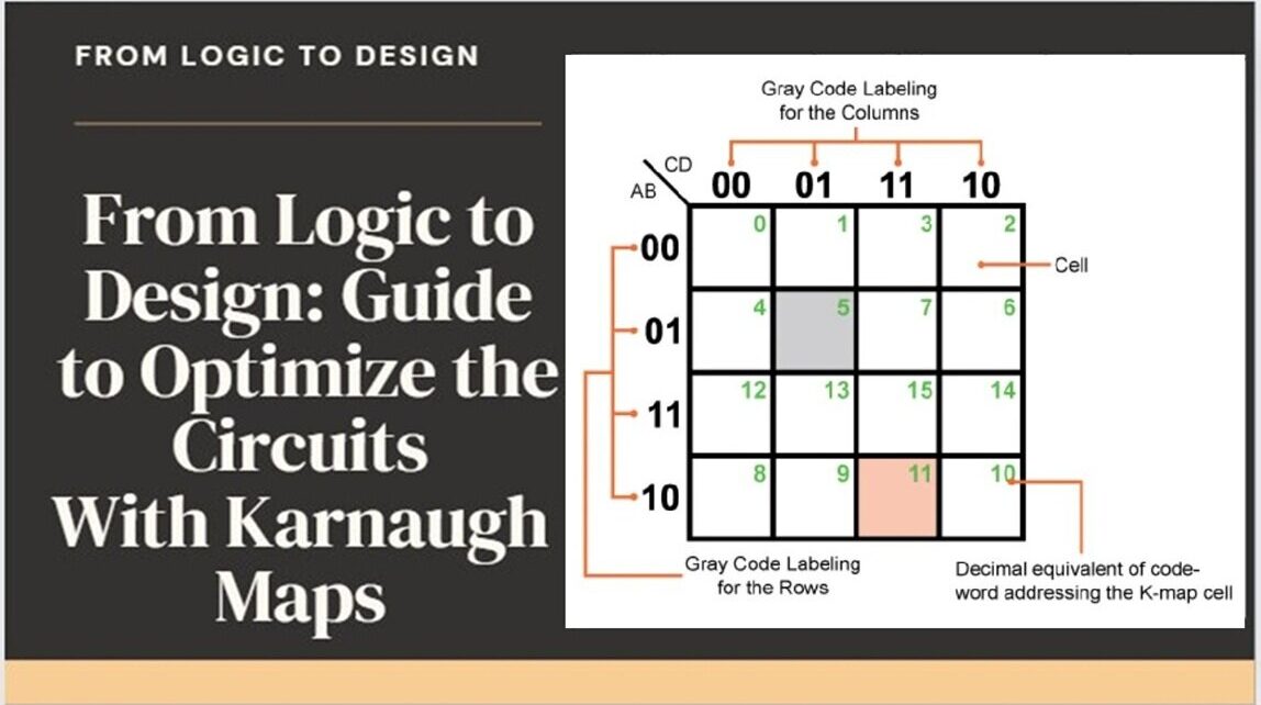
Furthermore, each cell within the k-map has a definite place value for this uses a specific encoding technique that is known as the gray coding.
What is the Gray Coding in Karnaugh Mapping?
A special technique encodes the logic and sets the place value in each cell of the K-map. This code’s specialty lies in ensuring that every adjacent cell value differs by only a single bit. For example, if the code word is 01, the previous and next code words must be 00 and 11, which can be arranged in any order, but cannot be 10 under any circumstances.
In the K-maps table, the rows and the columns of the table use Gray code-labeling that represents the values of the corresponding input variables. It means that each K-map cell can be highlighted by a unique Gray code word. For a better understanding of this concept view the below picture, which is used to simplify a logical expression of 4 variables that is mentioned in its top-left corner such as: (A, B, C, and D).

Understanding of Boolean Algebra and Logic Gates:
At the core of digital circuit design, Boolean algebra proved an essential part of the circuit framework that was developed by George Boole in the 19th century. Boolean algebra deals with variables that can have only two possible values: true (1) or false (0). This simplicity forms the basis for all digital computation and is implemented physically through logic gates.
Logic gates are essential components that carry out Boolean operations. These include AND, OR, NOT, NAND, NOR, XOR, and XNOR gates, each performing distinct logical functions on input signals.
Transitioning from Logic Expressions to Karnaugh Maps:
When designing digital circuits, it’s necessary to simplify complex Boolean expressions to reduce the number of gates and optimize performance. Karnaugh maps provide a visual and systematic method for simplifying Boolean expressions. Follow the below steps to convert the Boolean expression in a logic circuit.
Steps to Optimize the Circuits with Karnaugh Mapping:
- Define the Boolean Function: First select the Boolean expression derived from the logic requirements of the circuit that you need in your work.
- Construct the Karnaugh Map: Create an appropriate K-map grid depending on the number of variables, (typically 2, 3, or 4 dimensions) using the truth table formation.
- Plot the Minterms: For each combination of inputs that results in a true output, mark the corresponding cell in the K-map.
- Group Adjacent Minterms: Identify groups of 1s (minterms) that are adjacent in the K-map. Each group should ideally be a power of two in size (1, 2, 4, 8, etc.).
- Simplify the Expression: Each group corresponds to a simplified term in the Boolean expression. Combine these terms to create a simplified Boolean function.
- Implement the Circuit: Finally, convert the simplified Boolean expression back into a physical circuit using the appropriate logic gates.
To illustrate this step, we solve the practical example with detailed steps.
Understanding Karnaugh (K) Map with Example:
Consider the Boolean function F(A, B, C, D), which depends on four variables: A, B, C, and D. The function is defined as “F(A, B, C, D) = ∑ m(1, 3, 7, 11, 15) + d(0,2,5,8)”. Simplify this Boolean function using a Karnaugh map (K-map) and then convert the resulting simplified function into a digital circuit.
Solution:
Step 1:
First we have a Boolean function from the given statement.
Boolean Function = F(A,B,C,D)=∑ m(1,3,7,11,15) + d (0,2,5,8)
Min-terms = {1, 3, 7, 11, 15}, don’t-care terms = {0, 2, 5, 8}
Here, the function “F” depends on four variables: A, B, C, and D. The minterms “m” are where the function outputs a 1, and the don’t-care terms “d” can be either 0 or 1.
Step 2:
Construct the Karnaugh Map using the four variables then we need a 4×4 K-map.
Use the Karnaugh Map solver by Meracalculator to draw the 4×4 K-map by putting the functions values, minterms, and don’t-care terms & get the results with a single click.
| AB\CD | C’D’ | C’D | CD | CD’ |
|---|---|---|---|---|
| A’B’ | 0 | 1 | 3 | 2 |
| A’B | 4 | 5 | 7 | 6 |
| AB | 12 | 13 | 15 | 14 |
| AB’ | 8 | 9 | 11 | 10 |
Step 3:
To plot the corresponding minterms and “d” in the don’t-care cells.
| AB\CD | 00 | 01 | 11 | 10 |
|---|---|---|---|---|
| 00A | d | 1 | 1 | d |
| 01 | 0 | d | 1 | 0 |
| 11 | 0 | 0 | 1 | 0 |
| 10 | d | 0 | 1 | 0 |
Step 4:
Now, Identify and group the adjacent 1s and ds to create the largest groups possible. Ensure every 1 is included in at least one group.
The groups are visually represented in the K-map:

Step 5:
Now Simplify the Expression by converting to a simplified term in the Boolean expression.
- For the group of 4 cells = CD
- For two 1 with tow don’t care cell = A’B’
Thus simplified Boolean expression is:
F = A’B’+CD
Step 6:
Finally, convert the simplified Boolean expression into a physical circuit using logic gates.
- The term A’B’ can be used as a NOT gate and an AND gate.
- The term CD can be implemented using AND gates.
Combine these terms using an OR gate to obtain the final circuit:
- Use “NOT gate” for A’ and B’.
- Use “AND gate” for A’B’.
- Use “AND gate” CD.
- Also use the “OR gate” to combine A’B’ and CD.
Here is the final picture for digital circuits.

By following these steps, you can simplify the Boolean function and design an optimized digital circuit using Karnaugh mapping. This method reduces number of gates to increases the efficiency and performance of circuit.
Conclusion:
Karnaugh map technique is a helpful thing for digital circuit designers to design/convert complex Boolean logic into efficient circuit designs. By mastering the transition from logic to design through K-maps, engineers can achieve optimal performance in digital systems to ensure reliability and efficiency in modern electronics.
By reading this guide to theoretical understanding with practical application, the journey from logic to design becomes not only manageable but also produces an ability to make efficient digital circuits.
