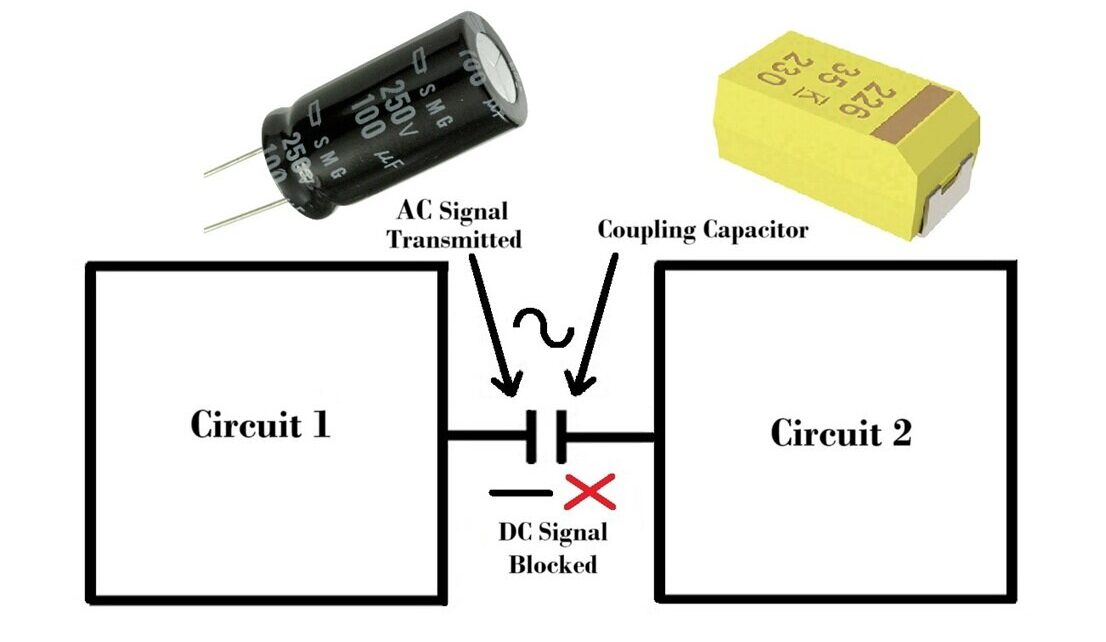
A coupling capacitor is a crucial component in electronic circuits, primarily used to transmit an AC signal from one stage of a circuit to another while blocking DC components. Here’s a detailed overview of its construction, working, value selection and Applications:
Construction of Capacitor:
The construction of a coupling capacitor involves creating a device that can store electrical energy in an electric field and allow AC signals to pass while blocking DC components. Here’s a detailed look into the construction of coupling capacitors:
Dielectric Material:
The dielectric is an insulating material placed between the two conductive plates. Its primary function is to increase the capacitor’s capacitance by reducing the electric field’s strength between the plates.
Common dielectric materials include:
Ceramic: Offers high stability and reliability, suitable for small capacitances.
Polyester (Mylar): Good for general-purpose applications with medium capacitance values.
Electrolytic: Provides higher capacitance values, often used when large capacitance is needed.
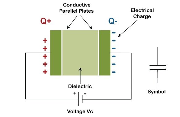
Conductive Plates (Electrodes):
These plates store the charge and are typically made of materials such as aluminum or tantalum. The electrodes are separated by the dielectric material.
Leads or Terminals:
These are the conductive leads that connect the capacitor to the circuit. They are typically made of metal wires.
Types of Coupling Capacitors:
Ceramic Capacitors:
Construction: Made by coating both sides of a thin ceramic dielectric with a metal film to form the electrodes.
Encapsulation: The assembly is usually coated with an insulating material.
Use: Preferred in high-frequency applications due to their low inductance and stable performance.
Polyester Capacitors:
Construction: Made by sandwiching a thin polyester film between two metal foils.
Encapsulation: The assembly is then rolled or stacked and coated with a protective plastic layer.
Use: Common in general-purpose applications, including coupling and decoupling.
Electrolytic Capacitors:
Construction: Consist of two aluminum foils, one of which is coated with an oxide layer that acts as the dielectric. The assembly is immersed in an electrolyte solution.
Encapsulation: The entire assembly is placed in a cylindrical aluminum casing and sealed.
Use: Suitable for applications requiring large capacitance values, such as power supply filtering.
Working of Capacitor:
AC Signal Transmission: The capacitor allows AC signals to pass through because an AC voltage causes the capacitor to charge and discharge continuously, thus transmitting the AC component of the signal.
DC Blocking: Since capacitors block DC after the initial charging phase, any DC offset or component present in the input signal is blocked, allowing only the AC component to pass through to the next stage of the circuit.
Use of Coupling Capacitors:

How to Choose the Value of the Coupling Capacitor:
Reactance Formula: The reactance (resistance) a capacitor changes with frequency:
Reactance = 1/2𝜋𝑓𝐶
Where,
𝑓 is the frequency and
𝐶 is the capacitance.
Frequency Dependency:
Determine the Cutoff Frequency:
The coupling capacitor forms a high-pass filter with the input impedance of the following stage. The cutoff frequency Fc of this filter is given by:
Fc = 1/(2π*Rin*C)
where Rin is the input resistance of the next stage and C is the capacitance.
Desired Frequency Response:
Choose Fc to be lower than the lowest frequency component of your AC signal to ensure minimal signal attenuation. For example, for audio applications, you might want Fc to be below 20 Hz.
Calculate the Capacitance:
Rearrange the cutoff frequency formula for C:
C = 1/(2π*Rin*Fc)
Substitute Rin and the desired Fc to find the appropriate capacitance.
Practical Considerations:
Ensure the capacitor’s voltage rating exceeds the maximum voltage it will experience in the circuit.
Select a capacitor type suitable for your application (e.g., electrolytic for larger values, ceramic for smaller values).
Example Calculation:
Assume you have a circuit with an input resistance Rin of 10 kΩ and you want a cutoff frequency Fc of 10 Hz.
Calculate the capacitance:
C = 1/(2π×10000×10) C = 1/628318 C ≈ 1.59μF
So, a 1.6 µF capacitor would be suitable for this application.
High frequencies: Low reactance, small capacitors (pF range).
Low frequencies: High reactance, large capacitors (µF range).
General Guidelines:
100 Hz Signal: Use a 10 µF capacitor.
1,000 Hz Signal: Use a 1 µF capacitor.
10,000 Hz (10 kHz) Signal: Use a 100 nF capacitor.
100,000 Hz (100 kHz) Signal: Use a 10 nF capacitor.
1,000,000 Hz (1 MHz) Signal: Use a 1 nF capacitor.
10,000,000 Hz (10 MHz) Signal: Use a 100 pF capacitor.
100,000,000 Hz (100 MHz) Signal: Use a 10 pF capacitor.
Parallel Resistance Adjustment:
Resistance ≤ 10 kΩ: The guidelines above apply.
Resistance > 10 kΩ: You can use smaller capacitors, roughly 1/10th of the recommended value.
Various applications Coupling capacitors:
Audio Circuits: To block DC components that can bias or damage speakers and audio amplifiers.
Amplifier Stages: To transfer the AC signal from one stage of an amplifier to the next without passing DC biasing conditions.
Signal Processing: In communication systems to ensure that only the desired AC signal is processed while blocking unwanted DC components.
How to Place a Coupling Capacitor in a Circuit:
Identify the Stages: Determine the points in the circuit where you need to block DC and allow AC to pass. Typically, this is between stages of an amplifier or between different functional blocks.
Series Connection: Place the coupling capacitor in series with the signal path. The capacitor should be connected such that one end is connected to the output of the first stage and the other end to the input of the subsequent stage.
Polarity: If using a polarized capacitor (like an electrolytic capacitor), ensure the correct polarity is maintained. The positive terminal should be connected to the side with higher DC potential.
By following these guidelines, you can effectively utilize coupling capacitors to ensure efficient AC signal transmission and DC blocking in various electronic circuits.
What are Passive Electronic Components and their Classification
