A Varistor is a voltage-dependent, non-linear resistor whose resistance changes significantly with applied voltage. The term varistor is derived from “variable resistor”, but unlike potentiometers or rheostats, its resistance varies automatically with voltage, not mechanically.
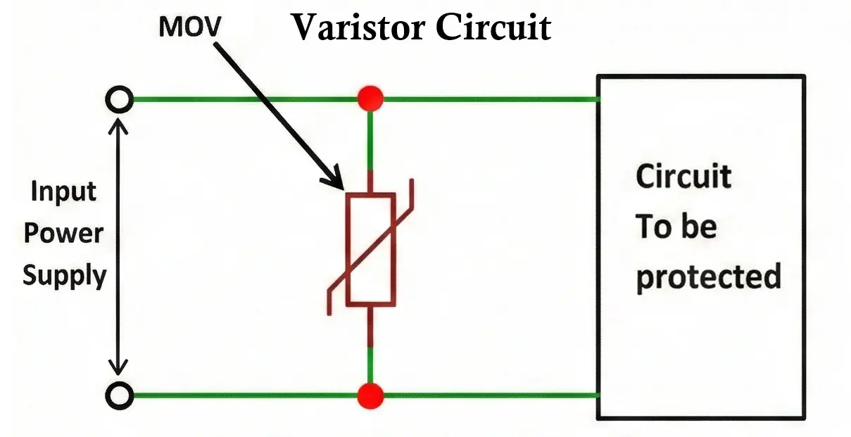
Varistors are primarily used for over-voltage protection. Under normal operating voltage, a varistor behaves like a very high resistance device. When the applied voltage exceeds a specified threshold, its resistance drops sharply, allowing it to divert excess energy and protect sensitive components.
Varistors are widely used in:
- Power supplies
- SMPS circuits
- Consumer electronics
- Industrial control systems
- Surge protectors
- Communication equipment
Varistor Symbol
The varistor symbol resembles a resistor symbol crossed by a diagonal line, indicating non-linear behavior.
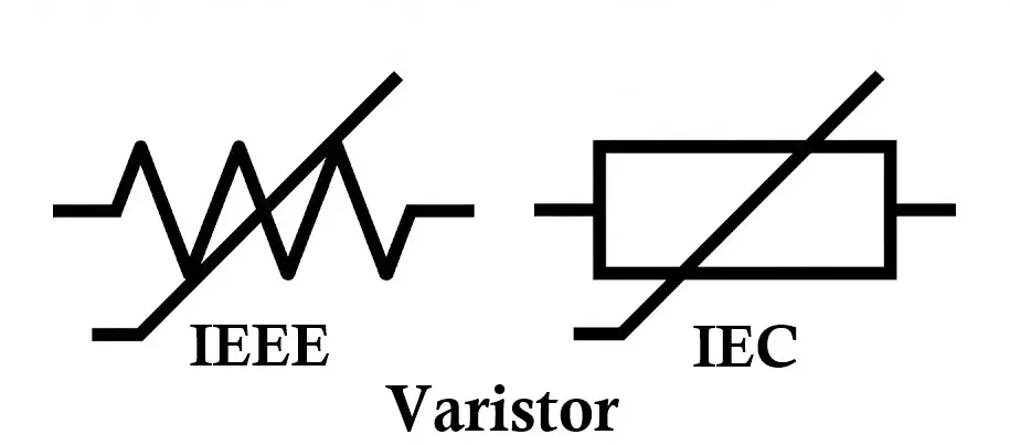
- The diagonal line represents voltage dependency
- The symbol is symmetrical → varistors are non-polarized
- Can be connected in either direction in AC or DC circuits
Related Articles:
- Types of Resistors with Symbol, Classification and Applications
- Fusible Resistor Construction, Working, Types and Applications
- Wire Wound Resistor Construction, Working, Types & Applications
- Carbon Composition Resistor Construction, Working & Applications
- Carbon Film Resistor Construction, Working, Types & Applications
- Metal Film Resistor Construction, Working, Types and Applications
- Metal Oxide Resistor Construction, Working, Types & Applications
- SMD Resistors Construction, Working, Types and Applications
- Trimmer Resistor Construction, Working, Types and Applications
- Rheostat Construction, Working, Types and Applications
- Thermistor Construction, Working, Types and Applications
Construction of Varistor
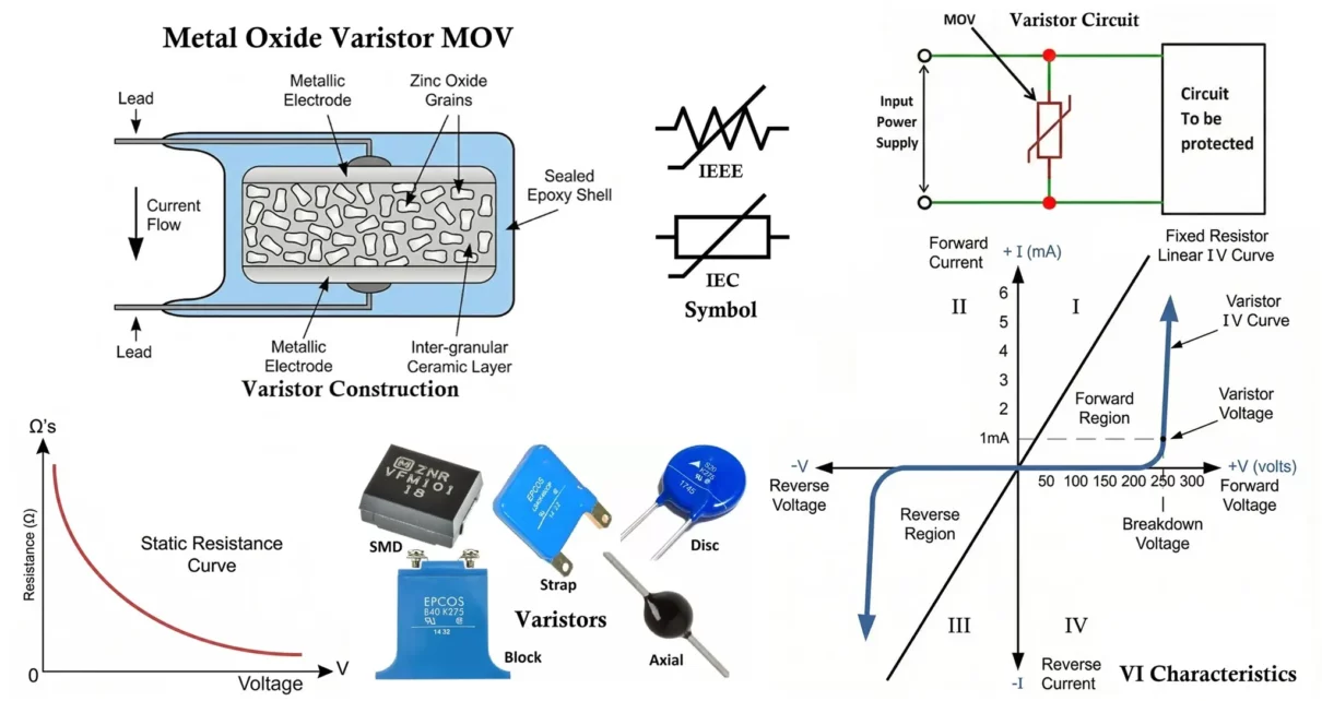
A varistor (Voltage Dependent Resistor, VDR) is a nonlinear semiconductor device designed to protect electrical and electronic circuits from transient over voltages. Its construction is engineered to produce a highly nonlinear voltage current (VI) characteristic, enabling it to act as a voltage-clamping device. Although several materials are used, the most common construction is based on zinc oxide (ZnO) technology.
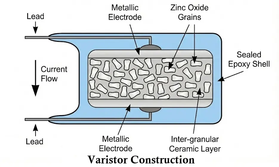
The construction of a typical varistor consists of the following components:
Ceramic Semiconductor Body
The core of a varistor is a sintered ceramic body composed primarily of zinc oxide (ZnO) grains, along with small amounts of metal oxide additives such as bismuth oxide, cobalt oxide, and manganese oxide.
Microstructure
- The device contains millions of microscopic ZnO grains.
- Grain boundaries between these particles form diode-like junctions.
- Each grain boundary behaves like a back-to-back diode pair.
- The collective effect of these grain boundary junctions produces the strong nonlinear behavior.
When a low voltage is applied, only a small leakage current flows. When the applied voltage exceeds a threshold value, the grain boundaries undergo avalanche breakdown, allowing a large current to pass and thereby clamping the voltage.
Electrode Layers
Metal electrodes are applied to the flat surfaces of the ceramic disc. These electrodes ensure uniform current distribution across the entire cross-sectional area of the device.
Common electrode materials include:
- Silver
- Aluminum
- Nickel-based conductive coatings
The electrodes are usually formed through screen printing followed by firing to ensure good adhesion and low contact resistance.
Lead Attachments
In radial or axial varistors, metallic leads are soldered or welded to the electrode surfaces. These leads provide electrical connection to the external circuit.
- Radial leads: Both leads extend from one side of the disc.
- Axial leads: Leads extend from opposite ends.
Lead design affects mounting configuration but does not alter internal operation.
Encapsulation / Coating
The assembled device is coated with an insulating protective layer, typically epoxy resin or a similar flame-retardant polymer.
The encapsulation provides:
- Electrical insulation
- Mechanical protection
- Moisture resistance
- Environmental durability
In higher-rated devices, additional protective features such as thermal cutoffs may be integrated to prevent overheating during fault conditions.
Manufacturing Process Overview
The construction process typically involves:
- Mixing zinc oxide powder with dopant metal oxides.
- Pressing the powder into disc shapes under high pressure.
- Sintering at high temperatures (approximately 1100–1300°C) to form a dense polycrystalline structure.
- Applying metal electrodes to both surfaces.
- Attaching leads (if required).
- Encapsulating and marking the device.
The sintering process is critical, as it determines grain size and grain boundary characteristics, which directly influence the breakdown voltage and nonlinearity coefficient.
Working of Varistor
A varistor operates as a nonlinear, voltage-dependent resistor that transitions from a high-resistance state to a low-resistance state when the applied voltage exceeds its rated value. Its operation can be explained in three stages:
Normal Voltage Condition
- Applied voltage is less than the rated varistor voltage.
- Grain boundary junctions remain non-conductive.
- The varistor behaves as a high-resistance device, effectively acting as an open circuit.
- Only a small leakage current (in the microampere range) flows through the device.
Under normal operating conditions, the varistor does not affect circuit performance.
Over-Voltage Condition
- Applied voltage exceeds the threshold (breakdown voltage).
- Grain boundary junctions undergo avalanche breakdown.
- The internal resistance drops sharply within nanoseconds.
- A large surge current flows through the varistor instead of the protected load.
- The excess voltage is clamped to a safe level, limiting potential damage to sensitive components.
During this stage, the varistor absorbs and dissipates transient energy in the form of heat.
After Surge
- The system voltage returns to its normal operating value.
- Avalanche conduction ceases.
- The varistor automatically returns to its high-resistance state.
- Only normal leakage current flows again.
- The protection cycle resets and is ready to respond to subsequent surge events.
This self-restoring characteristic enables the varistor to provide repeated overvoltage protection without external control or replacement, provided its energy rating is not exceeded.
Varistor Types
Varistors are classified mainly based on material composition and construction technology.
Types of Varistors Based on Material Composition
Varistors (Voltage Dependent Resistors, VDRs) are nonlinear resistive devices whose electrical characteristics depend strongly on the semiconducting material used in their construction. The material composition determines key performance parameters such as the nonlinearity coefficient (α), clamping voltage, leakage current, energy absorption capability, response time, and long-term stability. Based on material composition, varistors are classified into the following major types:
Silicon Carbide (SiC) Varistors
Silicon Carbide (SiC) varistors were among the earliest commercially developed varistors and were widely used before the introduction of zinc oxide technology. They are manufactured from sintered silicon carbide grains bonded together with a ceramic binder.
SiC varistors exhibit moderate nonlinear voltage-current characteristics compared to modern metal oxide varistors. Due to their relatively lower nonlinearity coefficient, they often require series spark gaps to improve surge protection performance. These devices typically have higher leakage currents and less precise clamping characteristics.
Despite these limitations, SiC varistors are mechanically robust and capable of handling substantial surge energy. Today, they are largely considered legacy devices and are mainly found in older industrial and power distribution systems.
Zinc Oxide (ZnO) Varistors (Metal Oxide Varistors – MOVs)
Zinc Oxide (ZnO) varistors, commonly referred to as Metal Oxide Varistors (MOVs), represent the most widely used varistor technology in modern electronic and power systems. They are composed primarily of zinc oxide grains combined with small amounts of bismuth, cobalt, manganese, and other metal oxides. The resulting polycrystalline ceramic structure creates numerous grain boundary junctions responsible for their highly nonlinear behavior.
ZnO varistors exhibit a very high nonlinearity coefficient (typically α ≈ 30–50), fast response times in the nanosecond range, and high surge current handling capability. They provide symmetrical voltage-current characteristics, making them suitable for both AC and DC applications.
These devices offer excellent clamping performance and compact size, making them ideal for consumer electronics, switch-mode power supplies (SMPS), AC line protection, and surge protection devices. However, ZnO varistors gradually degrade under repeated surge exposure, leading to increased leakage current and potential failure if overstressed.
Strontium Titanate (SrTiO₃) Varistors
Strontium Titanate (SrTiO₃) varistors are ceramic-based devices that exhibit nonlinear resistive characteristics. While less common than ZnO varistors, they are used in certain specialized electronic applications.
These varistors provide moderate nonlinearity and generally stable electrical characteristics over a range of operating temperatures. However, their energy absorption capability is typically lower than that of ZnO-based varistors, limiting their use in high-energy surge protection applications.
Due to their more limited commercial adoption, SrTiO₃ varistors are primarily found in specialized circuit designs rather than general-purpose surge suppression systems.
Polymer-Based Varistors (Composite Varistors)
Polymer-based varistors are constructed from conductive particles dispersed within a polymer matrix. Some of these devices exhibit voltage-dependent resistance characteristics, though they often combine varistor-like behavior with positive temperature coefficient (PTC) properties.
Compared to ceramic varistors, polymer-based devices generally have lower surge current capability and less pronounced nonlinearity. However, they offer advantages such as lightweight construction, mechanical flexibility, and compatibility with compact electronic assemblies.
These devices are typically used in low-voltage electronics and signal-line protection rather than high-energy power applications.
Types of Varistors Based on Construction
Varistors can be classified not only by material composition but also by their mechanical construction and packaging configuration. The construction type determines the device’s power rating, surge current capacity, mounting method, thermal performance, and suitability for specific applications. Based on construction, varistors are categorized as follows:
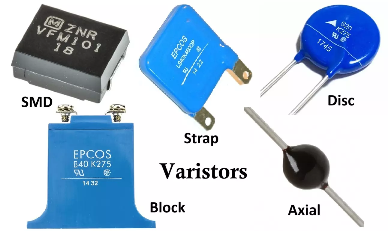
Disc-Type Varistors
Disc-type varistors are the most common construction form, particularly for metal oxide varistors (MOVs). They consist of a circular ceramic disc with metal electrodes applied to both flat surfaces and radial or axial leads attached for through-hole mounting.
This construction allows for efficient heat dissipation and high surge current capability. The disc diameter directly correlates with energy handling capacity—larger discs can absorb higher surge energy.
Disc-type varistors are widely used in:
- AC line surge protection
- Power supplies
- Consumer electronics
- Industrial control systems
They offer a good balance between cost, performance, and mechanical robustness.
Block-Type Varistors
Block-type varistors are rectangular or square-shaped devices designed for high-energy industrial and utility-grade applications. They are typically larger than disc types and may include mounting studs or terminal connections.
Due to their larger volume and improved thermal mass, block varistors can withstand significantly higher surge currents and energy levels. They are commonly installed in:
- Power distribution panels
- Motor control centers
- High-voltage surge arresters
- Industrial power systems
Block construction improves mechanical stability and enhances heat dissipation under heavy surge conditions.
Surface-Mount (SMD/Chip) Varistors
Surface-mount varistors, often referred to as chip varistors or multilayer varistors (MLVs), are compact devices designed for automated PCB assembly. They are typically constructed using multilayer ceramic technology, similar to multilayer ceramic capacitors.
These devices are optimized for low-voltage and low-energy transient suppression rather than high-energy surge protection. Their small size makes them suitable for:
- Mobile devices
- Communication circuits
- Data lines
- Consumer electronics PCBs
Although they offer fast response times, their surge current capability is significantly lower than disc or block types.
Multilayer Varistors (MLV)
Multilayer varistors are a specialized form of surface-mount construction. They consist of alternating layers of ceramic material and internal electrodes laminated together, creating a compact structure with enhanced electrical performance.
The multilayer configuration increases the effective active area within a small footprint, improving clamping characteristics and response time for low-voltage applications.
MLVs are commonly used for:
- ESD protection
- Signal line protection
- Automotive electronics
- High-density PCB designs
They are not intended for direct AC mains surge suppression due to limited energy capacity.
Radial-Lead and Axial-Lead Varistors
These classifications refer to the orientation of the leads rather than the internal material structure.
- Radial-lead varistors have both leads extending from one side of the disc. They are commonly used for PCB mounting and are the most prevalent configuration in consumer and industrial electronics.
- Axial-lead varistors have leads extending from opposite ends, similar to resistors. They are less common and typically used in specialized or legacy circuit designs.
Lead configuration affects board layout, mechanical mounting, and assembly method but does not significantly alter electrical behavior.
Encapsulated and Module-Type Varistors
For higher reliability and safety, some varistors are packaged inside protective housings or integrated into surge protection modules. These constructions may include:
- Thermal disconnect mechanisms
- Fuses
- Enclosures for environmental protection
Module-type varistors are commonly found in:
- Surge protection devices (SPDs)
- Power strips
- Industrial protection panels
This construction enhances safety by preventing catastrophic failure due to thermal runaway.
VI Characteristics of Varistor
The voltage current (VI) characteristic of a varistor is highly nonlinear, which distinguishes it from a conventional ohmic resistor. Instead of maintaining constant resistance, a varistor exhibits voltage-dependent resistance that decreases sharply once a specific threshold voltage is reached.
Non-Linear Voltage Current Relation
Electrically, a varistor can be modeled as a large number of series-parallel connected semiconductor junctions. The overall nonlinear relationship is expressed approximately by:
I = kVα
- I = current
- V = voltage
- k = material constant
- α = nonlinearity coefficient
For zinc oxide varistors, α typically ranges from 20 to 50, indicating strong nonlinear behavior. Higher α → better clamping performance.
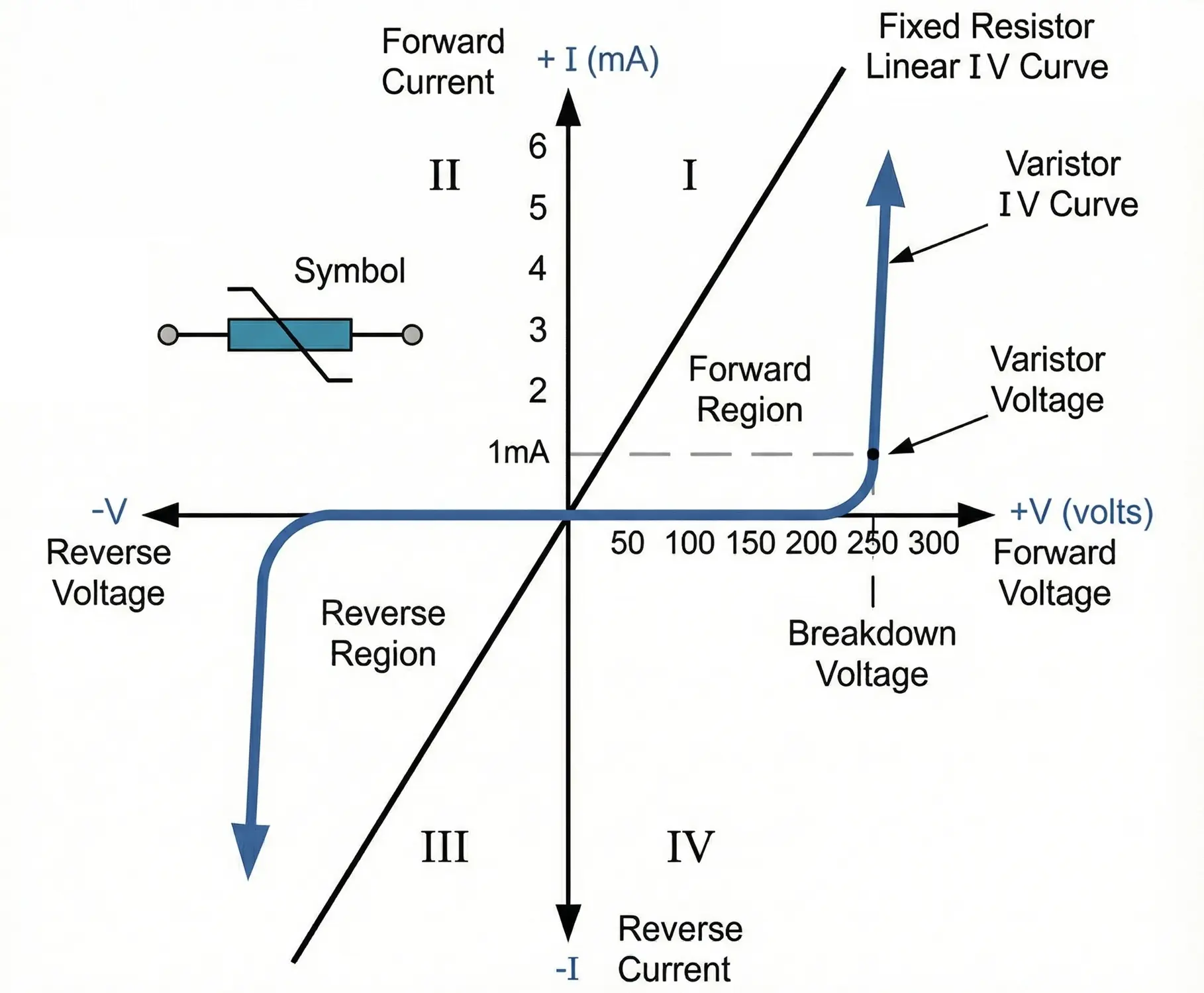
Regions of the VI Curve
The VI characteristic curve of a varistor can be divided into three main regions:
Leakage (Pre-Breakdown) Region
- Applied voltage is below the rated voltage.
- Current is extremely small (microampere range).
- The device behaves like a high-resistance insulator.
- The curve appears nearly flat in this region.
This is the normal operating region of the protected circuit.
Knee (Breakdown) Region
- Voltage approaches the rated varistor voltage.
- Current begins to increase rapidly.
- Nonlinear conduction starts at grain boundaries.
- This point is often referred to as the “knee voltage” or threshold voltage.
The transition in this region is very sharp for ZnO varistors.
Clamping (High-Conduction) Region
- Voltage slightly increases beyond the breakdown point.
- Current increases dramatically.
- Resistance drops to a very low value.
- The voltage across the device is effectively clamped.
In this region, the varistor conducts large surge currents to protect the connected equipment.
Key Features of the VI Curve
- Symmetrical characteristic for both positive and negative voltages (suitable for AC applications).
- Very fast response time (nanoseconds).
- Strong nonlinear slope determined by the α coefficient.
- Effective voltage clamping during transient surges.
Voltage Resistance (VR) Characteristic
The voltage resistance curve provides another way to understand varistor behavior.
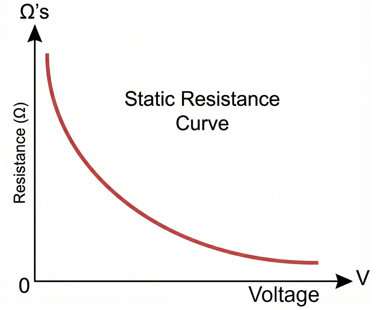
- At low voltage → Resistance is extremely high (megaohms).
- Near threshold voltage → Resistance decreases rapidly.
- At high voltage → Resistance becomes very low (few ohms or less).
Unlike a linear resistor (where resistance is constant), a varistor exhibits dynamic resistance, which changes with applied voltage.
Mathematically, resistance at any operating point is:
R = V/I
Since current increases exponentially with voltage, resistance decreases sharply as voltage increases.
How to Read Varistor Value
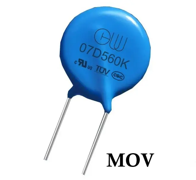
Varistor markings indicate maximum continuous voltage and size.
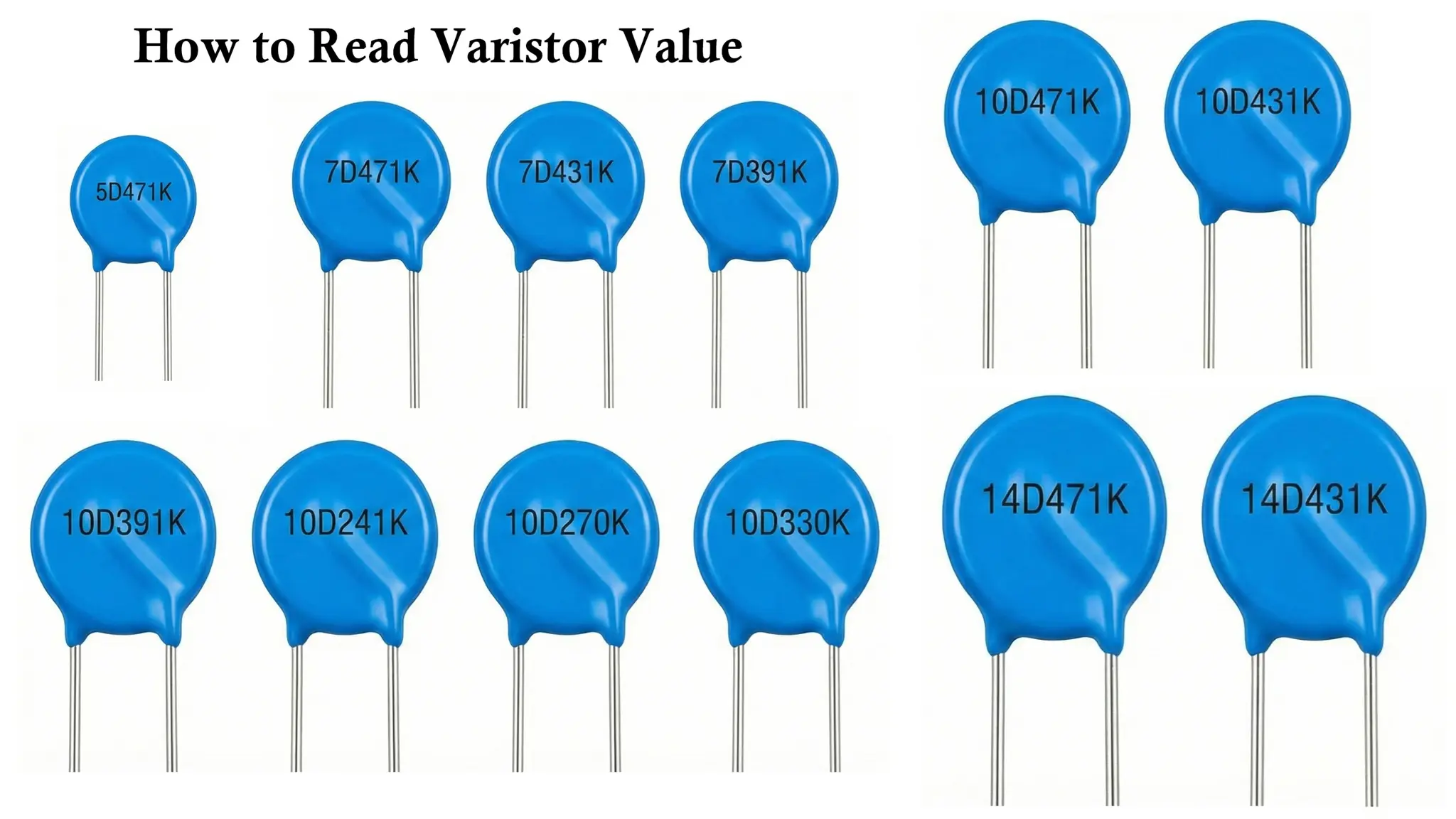
Example Marking: MOV 14D471K
- 14D → Disc diameter = 14 mm
- 471 → Varistor voltage
- 47 × 10¹ = 470 V
- K → Tolerance (±10%)
Common Voltage Ratings:
- 275V → 230V AC mains
- 420V → 380V AC systems
- 680V → Industrial equipment
Selection Criteria for Varistor
Choosing the correct varistor is critical for reliability and safety.
- Maximum Continuous Voltage
- AC RMS or DC voltage rating
- Must be higher than normal operating voltage
- Clamping Voltage
- Lower clamping voltage gives better protection
- Must not interfere with normal operation
- Energy Rating (Joules)
- Determines how much surge energy it can absorb
- Higher Joules = better durability
- Surge Current Rating
- Peak current it can safely conduct
- Important for lightning and switching surges
- Response Time
- MOVs respond in nanoseconds
- Suitable for fast transients
- Capacitance
- Important in high-frequency or data lines
- Lower capacitance preferred
Advantages of Varistors
- Fast Response Time
Varistors respond to transient over-voltages within nanoseconds, making them effective for suppressing lightning and switching surges. - High Surge Current Capability
They can absorb and dissipate significant surge energy within their rated limits. - Bidirectional Operation
Varistors exhibit symmetrical VI characteristics, enabling protection in both positive and negative voltage cycles, making them suitable for AC systems. - Compact and Cost-Effective
Metal oxide varistors (MOVs) are small, lightweight, and economical compared to many alternative protection devices. - Simple Installation
They can be connected directly across supply lines without requiring complex control circuitry. - Self-Restoring Operation
After a transient event, the device returns automatically to its high-resistance state (provided the energy rating is not exceeded).
Disadvantages of Varistors
- Gradual Degradation
Repeated surge exposure causes material degradation, leading to increased leakage current and reduced clamping effectiveness over time. - Limited Energy Rating
Excessive surge energy beyond the rated capacity can result in permanent failure. - Thermal Runaway Risk
Prolonged overvoltage conditions may cause overheating if thermal protection is not incorporated. - Leakage Current
A small leakage current flows even under normal operating voltage, which may not be suitable for highly sensitive circuits. - Limited Precision Clamping
Varistors clamp voltage within a range rather than at an exact fixed value.
Applications of Varistors
- Surge Protection in Power Systems
Installed across AC lines to protect equipment from lightning and switching transients. - Electronic Circuit Protection
Used in power supplies, adapters, and consumer electronics to guard against voltage spikes. - Industrial Equipment Protection
Applied in motor drives, control panels, and automation systems to suppress inductive switching surges. - Communication and Signal Line Protection
Low voltage varistors are used for electrostatic discharge (ESD) and transient suppression in signal circuits. - Automotive Electronics
Protect vehicle electrical systems from load dump and transient voltages. - Surge Protection Devices (SPDs)
Integrated into surge protectors and power distribution units for residential and commercial use.
Comparison Table: Varistor vs TVS vs Zener
| Parameter | Varistor (MOV) | TVS Diode | Zener Diode |
|---|---|---|---|
| Full Name | Metal Oxide Varistor | Transient Voltage Suppressor | Zener Voltage Regulator Diode |
| Primary Function | Surge protection (AC/DC lines) | Fast transient suppression | Voltage regulation / reference |
| Response Time | Slow (~ns to µs) | Very fast (ps to ns) | Moderate (ns) |
| Clamping Accuracy | Poor to moderate | Good | Very precise |
| Energy Handling | Very high (large surge currents) | Moderate to high | Low |
| Peak Current Capability | Very high (kA range) | High (tens to hundreds of A) | Low (mA to a few A) |
| Degradation Over Time | Yes (wears out with surges) | Minimal (unless overstressed) | Minimal (within ratings) |
| Leakage Current | Low (below threshold) | Very low | Moderate |
| Capacitance | High | Low to moderate | Low |
| Bidirectional Operation | Yes (inherently) | Available (uni/bi-directional types) | Typically unidirectional |
| Typical Applications | Mains surge protection | ESD, lightning, fast spikes | Voltage regulation circuits |
| Cost | Low | Moderate | Very low |
Summary Table
| Parameter | Varistor |
|---|---|
| Type | Non-linear resistor |
| Polarity | Non-polarized |
| Main Material | Zinc Oxide |
| Working Principle | Voltage-dependent resistance |
| Response Time | Nanoseconds |
| Energy Handling | High |
| Typical Voltage Range | 18V – 1800V |
| Common Type | MOV |
| Main Use | Surge & transient protection |
Conclusion
A Varistor is an essential protection component in modern electronic systems. Its ability to clamp over-voltages rapidly and absorb high surge energy makes it indispensable in power electronics and industrial equipment. Understanding its construction, characteristics, and correct selection ensures longer circuit life, higher reliability, and improved safety.
Types of Resistors with Symbol, Classification and Applications
Light Dependent Resistor (LDR) / Photoresistor Circuit Diagram & Working
