A trimmer resistor, commonly known as a trim-pot (trimming potentiometer), is a small adjustable resistor designed for fine-tuning, calibration, and preset adjustment of electronic circuits. Unlike standard potentiometers that are frequently adjusted by the user, trimmer resistors are usually set once during manufacturing, testing, or servicing, and then left unchanged for long periods.
- Trimmer resistors play a critical role in:
- Voltage calibration
- Gain and offset adjustment
- Frequency tuning
- Sensor threshold setting
- Bias current adjustment
They are widely used in analog electronics, power supplies, amplifiers, sensor interfaces, instrumentation, and embedded systems.
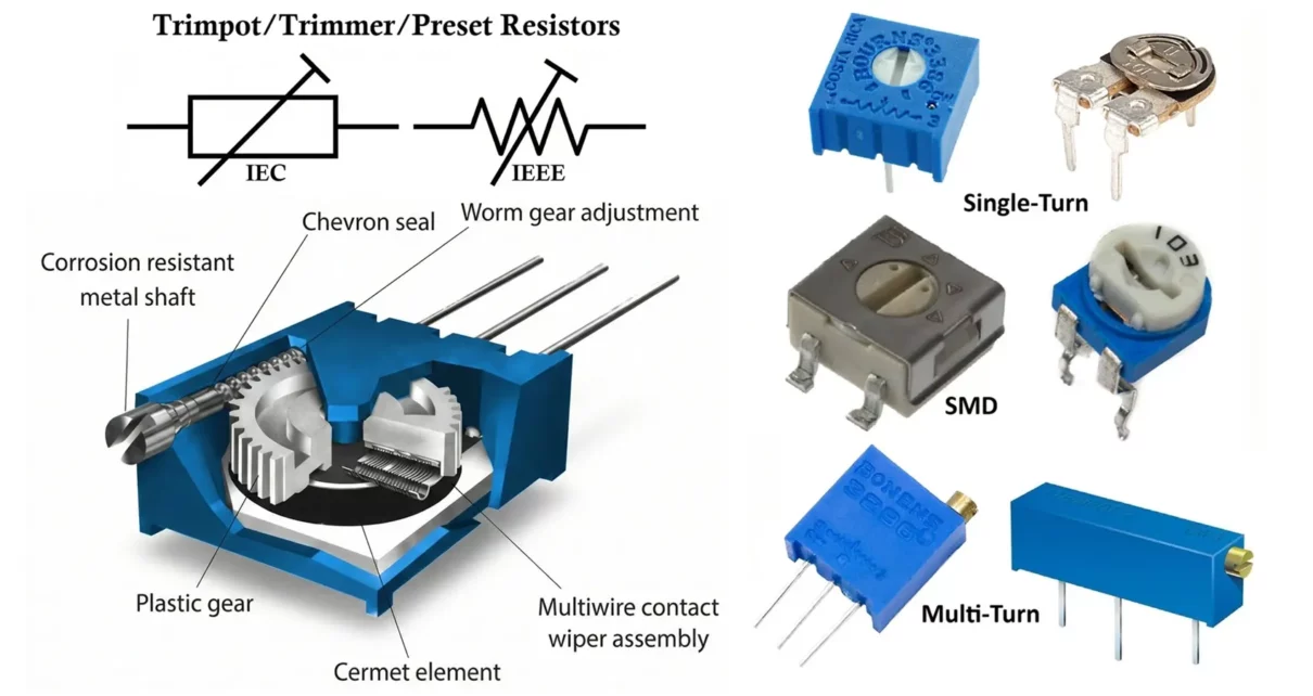
Trimmer Resistor Symbol
The symbol of a trimmer resistor is similar to that of a potentiometer or variable resistor, with a few variations depending on standards:
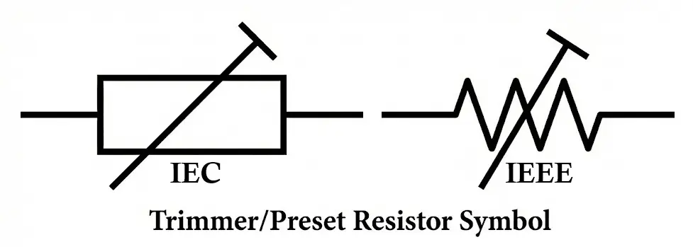
- Resistive element shown as a zigzag line (IEEE) or rectangle (IEC)
- Three terminals:
- Two fixed end terminals
- One adjustable wiper
- A diagonal arrow or screwdriver mark indicates adjustability
- Common Symbol Variants
- 3-terminal trimmer (potentiometer mode)
- 2-terminal trimmer (rheostat mode)
- Preset resistor symbol (often marked “VR” or “TR”)
Related Articles:
- Types of Resistors with Symbol, Classification and Applications
- Fusible Resistor Construction, Working, Types and Applications
- Wire Wound Resistor Construction, Working, Types & Applications
- Carbon Composition Resistor Construction, Working & Applications
- Carbon Film Resistor Construction, Working, Types & Applications
- Metal Film Resistor Construction, Working, Types and Applications
- Metal Oxide Resistor Construction, Working, Types & Applications
- SMD Resistors Construction, Working, Types and Applications
- Rheostat Construction, Working, Types and Applications
Construction of Trimmer Resistor
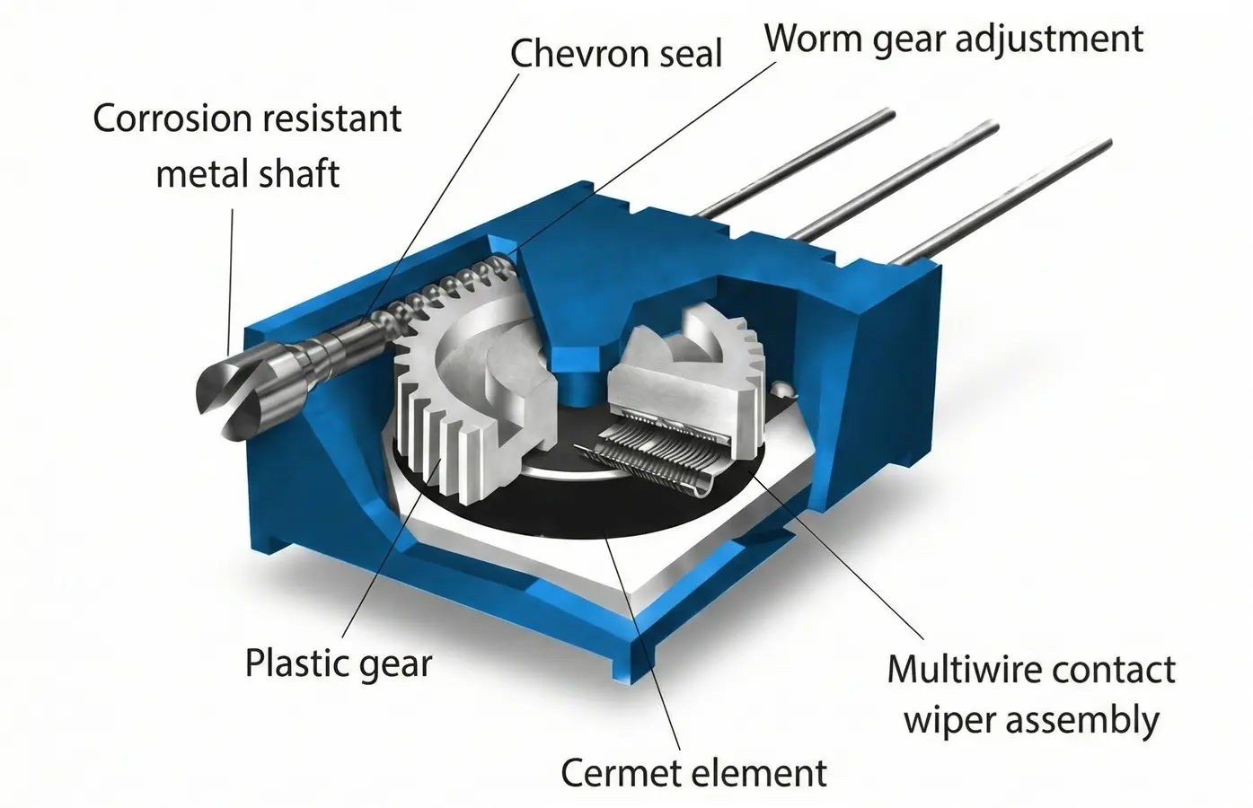
Basic Structural Elements
A trimmer resistor consists of the following main parts:
- Resistive Track
- Made of carbon, cermet, conductive plastic, or wire
- Determines the resistance value and power rating
- Wiper (Slider)
- Metallic contact that slides or rotates over the resistive element
- Connected to the adjustment screw
- Adjustment Mechanism
- Screw-driven rotary or linear actuator
- Adjusted using a screwdriver or trimming tool
- Terminals / Leads
- Usually, 2 or 3 metal pins
- Designed for PCB mounting
- Housing
- Molded plastic or ceramic body
- Protects internal components from dust and mechanical damage
Materials Used
| Component | Common Materials |
|---|---|
| Resistive track | Carbon, cermet, conductive polymer |
| Wiper | Phosphor bronze, beryllium copper |
| Body | Plastic, epoxy, ceramic |
| Terminals | Tin-plated copper |
Working Principle of Trimmer Resistor
The operation of a trimmer resistor is based on variable resistance through mechanical adjustment.
Operating Mechanism
- When the adjustment screw is rotated:
- The wiper moves along the resistive track
- The effective resistance between terminals changes
- The output voltage or current in the circuit varies accordingly
Modes of Operation
- Potentiometer Mode (3-Terminal)
- Acts as a voltage divider
- Used for reference voltage and calibration
- Rheostat Mode (2-Terminal)
- Used to control current
- One terminal and the wiper are connected together
Electrical Characteristics of Trimmer Resistors
- Resistance Range
- Typical values: 10Ω to 10MΩ
- Most common ranges: 1kΩ, 10kΩ, 100kΩ, 1MΩ
- Power Rating
- Generally low power: 0.05W to 0.5W
- Not suitable for high-current applications
- Tolerance
- Common tolerance: ±10% to ±20%
- Precision trimmers may offer ±5%
- Temperature Coefficient (TCR)
- Carbon: Higher TCR (less stable)
- Cermet: Lower TCR (better stability)
- Resolution
- Depends on number of turns and type of resistive element
- Multi-turn trimmers provide very fine adjustment
How to Read Trimmer Resistor Value
- Numerical Marking System
- Most trimmer resistors use a 3-digit code, similar to fixed resistors:
- First two digits → significant figures
- Third digit → multiplier (number of zeros)
- Most trimmer resistors use a 3-digit code, similar to fixed resistors:
- Examples:
- 103 → 10 × 10³ = 10kΩ
- 502 → 50 × 10² = 5kΩ
- 104 → 10 × 10⁴ = 100kΩ
- Letter Codes
- K → kilo-ohms
- M → mega-ohms
- R → decimal point (e.g., 4R7 = 4.7Ω)
- Datasheet Reference
- For precision or multi-turn trimmers, always refer to:
- Manufacturer datasheet
- Series number and resistance code
- For precision or multi-turn trimmers, always refer to:
Types of Trimmer Resistors
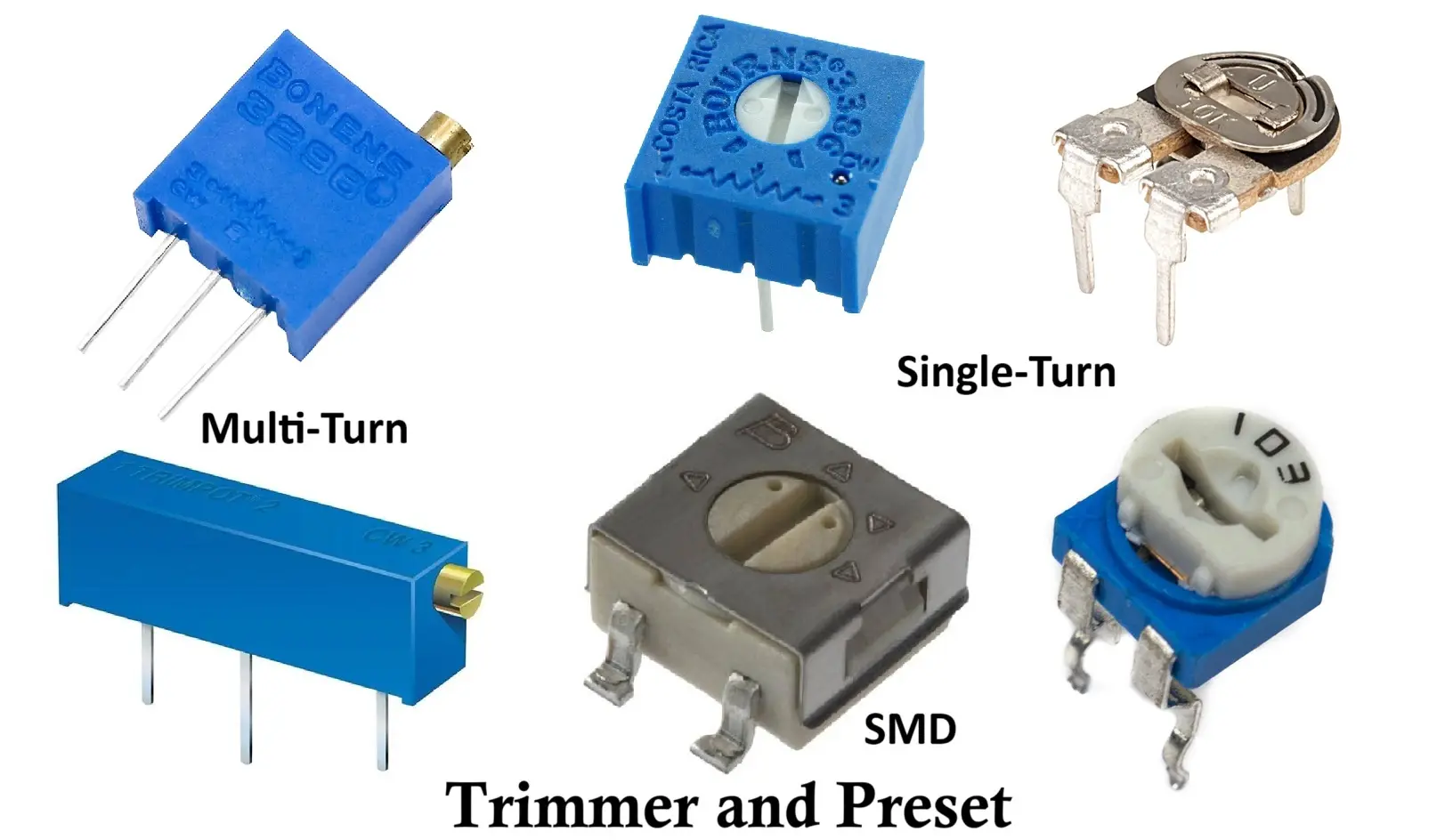
- Based on Number of Turns
- Single-Turn Trimmers
- Full resistance changes in one rotation
- Faster adjustment
- Lower precision
- Multi-Turn Trimmers
- Typically, 5, 10, or 20 turns
- Very fine control
- High accuracy and stability
- Single-Turn Trimmers
- Based on Mounting Style
- Through-Hole Trimmer
- Surface Mount (SMD) Trimmer
- Vertical Mount
- Horizontal Mount
- Based on Resistive Material
- Carbon: Low cost, moderate stability
- Cermet: High precision, low drift
- Conductive plastic: Smooth adjustment, low noise
- Wire-wound: High power capability, inductive effects
Selection Criteria for Trimmer Resistors
When choosing a trimmer resistor, consider:
- Resistance value and range
- Number of turns required
- Power rating
- Tolerance and stability
- Temperature coefficient
- PCB space and mounting orientation
- Environmental conditions (humidity, vibration)
- Adjustment frequency
- Mechanical life (number of adjustments)
Advantages of Trimmer Resistors
- Compact size
- Precise calibration capability
- Low cost
- Easy PCB integration
- Suitable for factory preset adjustments
- Available in wide resistance ranges
- Supports analog fine-tuning
Disadvantages of Trimmer Resistors
- Limited power handling
- Mechanical wear over time
- Not suitable for frequent user adjustment
- Susceptible to dust and oxidation (low-quality types)
- Adjustment may drift due to vibration or temperature
- Requires tool for adjustment
Applications of Trimmer Resistors
Trimmer resistors are widely used in:
- Power supply voltage calibration
- Op-amp offset and gain adjustment
- Audio amplifier bias setting
- Sensor threshold calibration
- Oscillator frequency tuning
- Reference voltage trimming
- Embedded system analog inputs
- Battery charging circuits
- Instrumentation and measurement equipment
- Industrial control electronics
Summary Table
| Parameter | Description |
|---|---|
| Component Name | Trimmer Resistor (Trimpot) |
| Function | Fine adjustment and calibration |
| Typical Resistance Range | 10Ω – 10MΩ |
| Power Rating | 0.05W – 0.5W |
| Terminals | 2 or 3 |
| Adjustment Type | Screw-based |
| Turns | Single-turn / Multi-turn |
| Mounting | Through-hole / SMD |
| Accuracy | Moderate to high (multi-turn) |
| Common Materials | Carbon, cermet, conductive plastic |
| Applications | Calibration, tuning, biasing |
Conclusion
The trimmer resistor is an essential component in precision electronics, enabling accurate adjustment and calibration of circuit parameters. While simple in appearance, its correct selection and application significantly impact circuit performance, stability, and reliability. Understanding its construction, working principles, characteristics, and limitations allows engineers and hobbyists to design more accurate, efficient, and robust electronic systems.
Types of Resistors with Symbol, Classification and Applications
Wire Wound Resistor Construction, Working, Types and Applications
