A thermistor is a temperature-sensitive passive electronic component whose resistance changes significantly with temperature. The term thermistor is derived from Thermally sensitive resistor. Unlike standard resistors whose resistance remains nearly constant over temperature, thermistors are designed to exhibit large, predictable resistance variations with temperature changes.
Thermistors are widely used in:
- Temperature measurement and control
- Over-temperature protection
- Inrush current limiting
- Battery management systems (BMS)
- Consumer electronics, automotive, industrial, and medical systems
Their high sensitivity, small size, low cost, and fast response make thermistors indispensable in modern electronics.
Thermistor Symbol
In circuit diagrams, a thermistor is represented by a resistor symbol with an additional diagonal line and temperature marking.
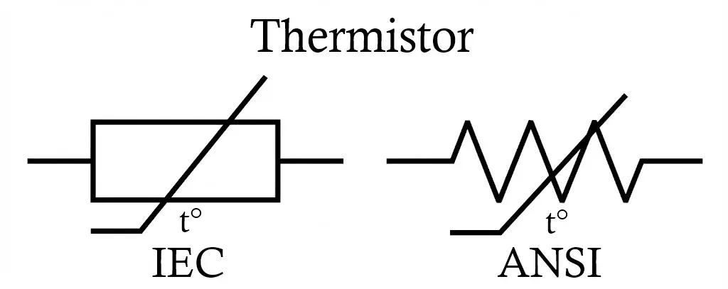
- The base symbol is a standard resistor
- A diagonal line or “T” indicates temperature dependence
- Sometimes marked explicitly as NTC or PTC
The symbol does not change functionally between NTC and PTC; the distinction is specified in the component designation.
Related Articles:
- Types of Resistors with Symbol, Classification and Applications
- Fusible Resistor Construction, Working, Types and Applications
- Wire Wound Resistor Construction, Working, Types & Applications
- Carbon Composition Resistor Construction, Working & Applications
- Carbon Film Resistor Construction, Working, Types & Applications
- Metal Film Resistor Construction, Working, Types and Applications
- Metal Oxide Resistor Construction, Working, Types & Applications
- SMD Resistors Construction, Working, Types and Applications
- Trimmer Resistor Construction, Working, Types and Applications
- Rheostat Construction, Working, Types and Applications
Construction of Thermistor
Thermistors are made from semiconductor ceramic materials, primarily metal oxides.
Materials Used
Common oxides include:
- Manganese oxide (MnO)
- Nickel oxide (NiO)
- Cobalt oxide (CoO)
- Copper oxide (CuO)
- Iron oxide (Fe₂O₃)
Different oxide combinations determine the temperature coefficient and resistance value.
Manufacturing Process
- Metal oxide powders are carefully mixed
- The mixture is pressed into beads, discs, or chips
- Sintering is performed at high temperatures
- Lead wires are attached (for THT types)
- Encapsulation using epoxy, glass, or resin
Encapsulation Types
- Epoxy coated – low cost, moderate stability
- Glass sealed – high precision, long-term stability
- Metal probe housing – industrial and harsh environments
Types of Thermistors
A thermistor is a temperature-sensitive resistor whose resistance changes significantly with temperature. Thermistors are classified based on the sign of their temperature coefficient of resistance (TCR):
- PTC (Positive Temperature Coefficient) Thermistor
- NTC (Negative Temperature Coefficient) Thermistor
Temperature Resistance Relationship
For small temperature variations, the change in resistance can be approximated as:
dR = kdT
Where:
- dR = Change in resistance
- dT = Change in temperature
- k = Temperature coefficient of resistance
- If k > 0 → Resistance increases with temperature → PTC
- If k < 0 → Resistance decreases with temperature → NTC
Note: This linear equation is only a local approximation. Thermistors are inherently nonlinear devices.
PTC (Positive Temperature Coefficient) Thermistor
A PTC thermistor is a thermistor whose resistance increases with an increase in temperature and decreases with a decrease in temperature.
dR/dT > 0
Construction
Most switching-type PTC thermistors are made from polycrystalline ceramic materials, typically doped barium titanate (BaTiO₃).
They are available in disc, chip, and surface-mount packages.
Electrical Behavior
- At low temperatures → Small increase in resistance
- Near the switching temperature (TR) or Curie temperature → Resistance increases sharply
- Above TR → Resistance rises exponentially
This sharp transition makes PTC thermistors ideal for protection circuits.
Types of PTC Thermistors
- Silistor (Linear PTC)
- Made from silicon
- Exhibits approximately linear increase in resistance
- Used mainly for temperature sensing applications
- Switching-Type PTC (Ceramic PTC)
- Made from polycrystalline ceramic
- Slight NTC region at lower temperatures
- Sharp exponential resistance increase at Curie temperature
- Used for:
- Overcurrent protection
- Motor winding protection
- Self-regulating heaters
- Inrush current limiting
Advantages of PTC Thermistor
- Provides automatic overcurrent protection
- Efficient and safe motor starting
- Self-regulating behavior
- Compact size
- Cost-effective
- No external control circuit required in protection applications
Disadvantages of PTC Thermistor
- Less sensitive compared to NTC thermistors
- Affected by self-heating (I²R losses)
- Limited operating temperature range
- Nonlinear response (except silistor type)
Applications of PTC Thermistor
- Overcurrent protection circuits
- Resettable fuse (PPTC) applications
- Motor winding protection
- Transformer protection
- Inrush current limiting
- Self-regulating heaters
- Battery pack protection
- SMPS and power supply protection
NTC (Negative Temperature Coefficient) Thermistor
An NTC thermistor is a thermistor whose resistance decreases with increasing temperature.
dR/dT < 0
Construction
NTC thermistors are typically made from sintered metal oxides, such as:
- Manganese (Mn)
- Nickel (Ni)
- Cobalt (Co)
- Copper (Cu)
They are available in bead, disc, glass-encapsulated, and epoxy-coated forms.
Electrical Behavior
NTC thermistors exhibit a strongly nonlinear exponential relationship between resistance and temperature:
R(T) = R0 × eβ(1/T − 1/T0)
Where:
- R0 = Resistance at reference temperature T0 (usually 25°C)
- β = Material constant
- T = Absolute temperature in Kelvin
As temperature increases, resistance decreases rapidly.
Advantages of NTC Thermistor
- Very high temperature sensitivity
- Fast thermal response (low thermal mass)
- Small size and lightweight
- Low cost
- Wide resistance range (ohms to megaohms)
- Good accuracy over limited temperature range
- Simple interface circuitry
Disadvantages of NTC Thermistor
- Highly nonlinear characteristics
- Limited temperature range compared to thermocouples
- Self-heating error at higher currents
- Requires calibration/linearization for precision use
- Long-term stability lower than RTDs
Applications of NTC Thermistor
- Temperature sensing and measurement
- Digital thermometers
- HVAC temperature sensors
- Battery temperature monitoring (BMS)
- Inrush current limiting in power supplies (SMPS)
- Medical temperature probes
- Consumer electronics temperature control
- Automotive temperature sensing
Comparison Between PTC and NTC Thermistors
| Parameter | NTC Thermistor | PTC Thermistor |
|---|---|---|
| Temperature coefficient | Negative | Positive |
| Resistance change | Decreases with temperature | Increases with temperature |
| Sensitivity | Very high | Moderate |
| Linearity | Poor (non-linear) | Poor (step-like) |
| Typical use | Temperature sensing | Protection |
| Response time | Fast | Moderate |
| Cost | Low | Low |
| Common packages | Bead, disc, SMD | Disc, polymer |
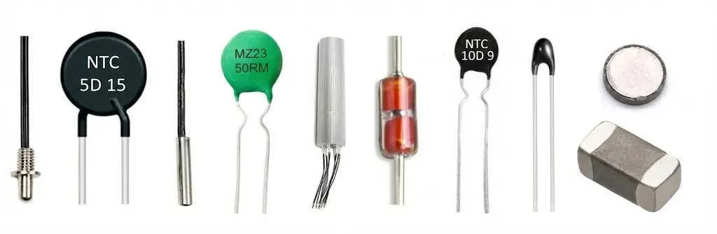
Types of Thermistors Based on Construction and Form
Thermistors are classified by their physical construction and mounting configuration as follows:
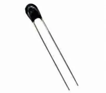
1. Bead Thermistors
Small, spherical ceramic beads with axial leads, often glass coated. They offer very fast response due to low thermal mass and are used in precision temperature sensing and medical applications.
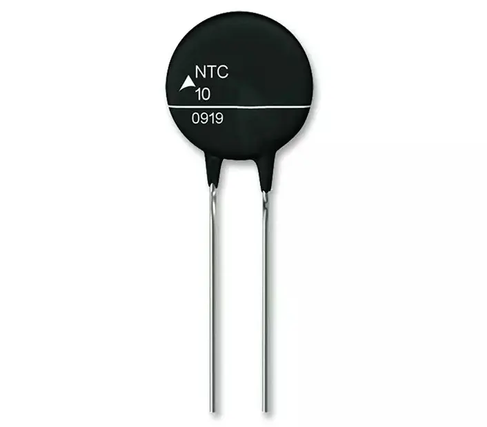
2. Disc (Chip) Thermistors
Flat ceramic discs with metalized surfaces and radial leads. They provide good stability and moderate power handling, commonly used in temperature compensation and circuit protection.
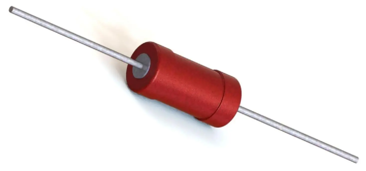
3. Rod (Cylindrical) Thermistors
Cylindrical elements with axial leads and protective coating. They handle higher power and are suitable for industrial and power control applications.
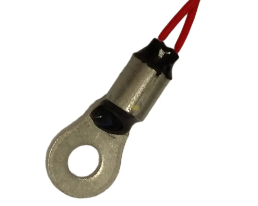
4. Washer (Ring) Thermistors
Ring-shaped thermistors with a central hole for bolt mounting. Designed for direct surface contact, widely used in motor and heat sink temperature monitoring.
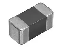
5. Surface-Mount (SMD) Thermistors
Miniature rectangular chips for PCB mounting. Compact, fast-responding, and ideal for consumer electronics and battery management systems.
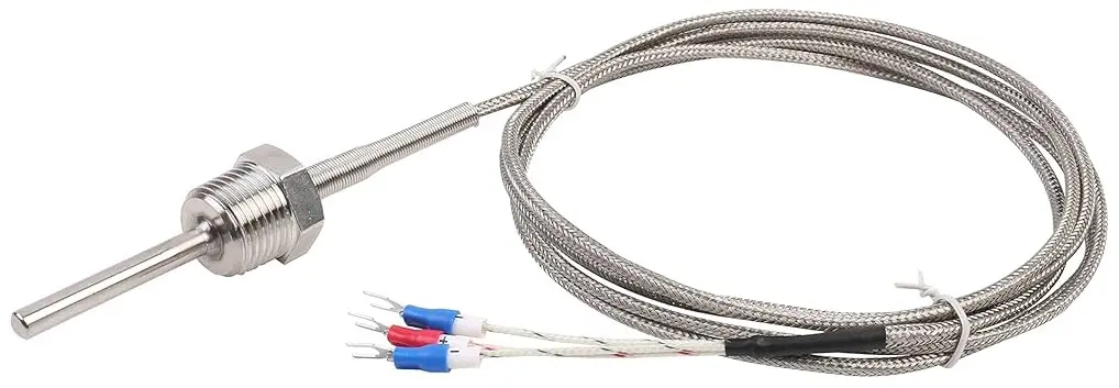
6. Probe-Type Thermistors
Thermistors enclosed in protective metal or plastic probes. Used in HVAC, industrial process control, and liquid temperature measurement.
Summary Table
| Type | Size | Response Speed | Power Handling | Typical Use |
|---|---|---|---|---|
| Bead | Very small | Very fast | Low | Precision sensing |
| Disc | Medium | Moderate | Medium | Compensation / protection |
| Rod | Larger | Slower | Higher | Power systems |
| Washer | Medium | Moderate | Medium–High | Surface mounting |
| SMD | Very small | Fast | Low | PCB electronics |
| Probe | Varies | Moderate | Varies | Industrial / HVAC |
Types of Thermistors Based on Material
Thermistors are classified by the base material used in their construction, which determines their temperature coefficient, sensitivity, and operating range.
1. Metal Oxide (Ceramic) Thermistors
Fabricated from sintered semiconductor oxides such as manganese, nickel, cobalt, or copper oxides. These are predominantly NTC (Negative Temperature Coefficient) devices and exhibit an exponential resistance–temperature relationship. They offer high sensitivity and stability and are widely used for temperature sensing and inrush current limiting.
2. Polymer Thermistors (PPTC)
Constructed from a conductive polymer matrix embedded with carbon particles. These are typically PTC (Positive Temperature Coefficient) devices and display a sharp resistance increase at a defined transition temperature. They are commonly used as resettable overcurrent protection devices.
3. Silicon Thermistors
Manufactured from doped silicon semiconductor material. They provide a more linear temperature response compared to ceramic NTC thermistors and offer high repeatability and precision, making them suitable for integrated and automotive temperature sensing applications.
4. Glass-Encapsulated Thermistors
Usually ceramic (metal oxide) thermistors sealed in a glass package. The glass encapsulation enhances thermal stability, chemical resistance, and high-temperature capability, enabling operation in harsh environments.
This material-based classification is essential for selecting a thermistor according to accuracy requirements, environmental conditions, and circuit function.
Summary Table
| Material Type | Typical Coefficient | Temperature Range | Main Application |
|---|---|---|---|
| Metal Oxide (Ceramic) | NTC (mostly) | -55°C to 300°C | Temperature sensing |
| Polymer | PTC | 0°C to 150°C | Resettable fuse |
| Silicon | NTC (linear) | -50°C to 150°C | Precision sensing |
| Glass-encapsulated (ceramic core) | NTC | Up to 500°C | Harsh environments |
Working Principle of Thermistor
The operation of a thermistor is based on temperature-dependent semiconductor conductivity.
NTC Thermistor Working
- At low temperature, fewer charge carriers are available
- Resistance is high
- As temperature increases:
- Thermal energy excites more electrons
- Carrier concentration increases
- Electrical resistance decreases rapidly
PTC Thermistor Working
- At normal temperature, resistance is low
- Beyond a critical temperature:
- Crystal lattice structure changes
- Charge carrier mobility reduces
- Resistance increases sharply
This behavior allows PTC thermistors to act as self-resetting protection devices.
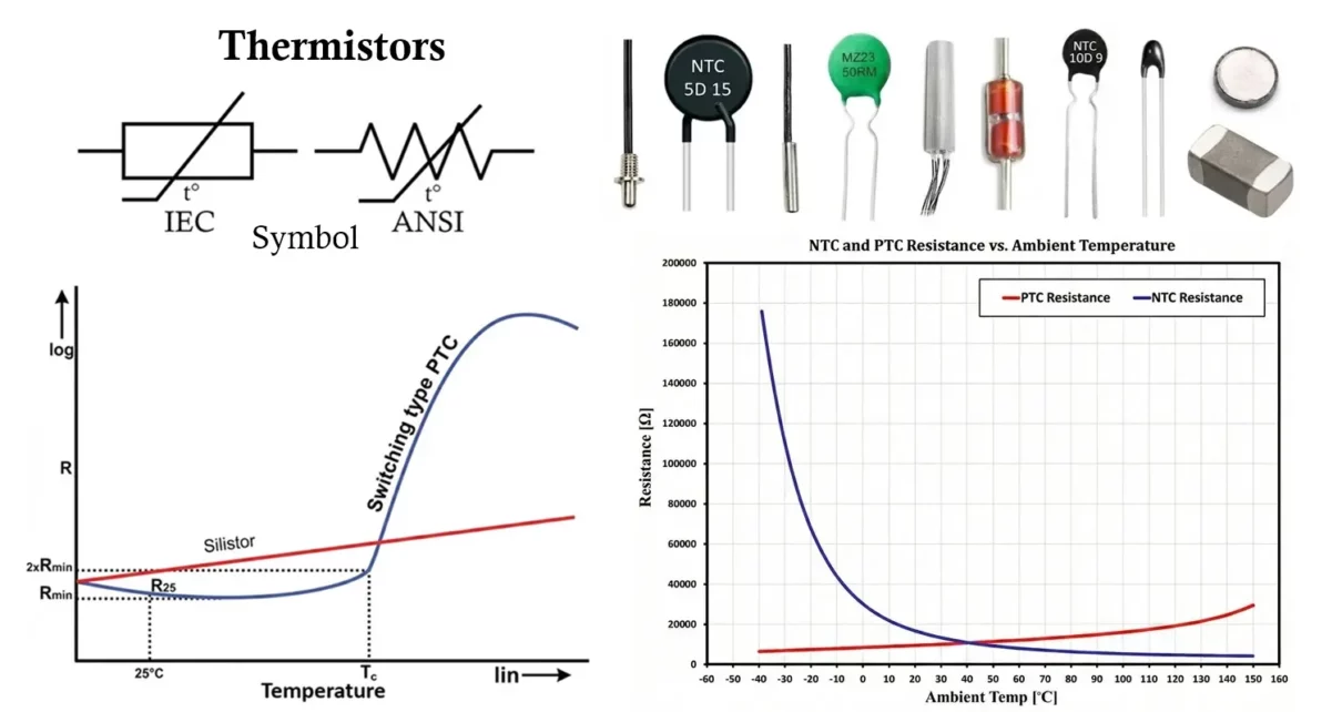
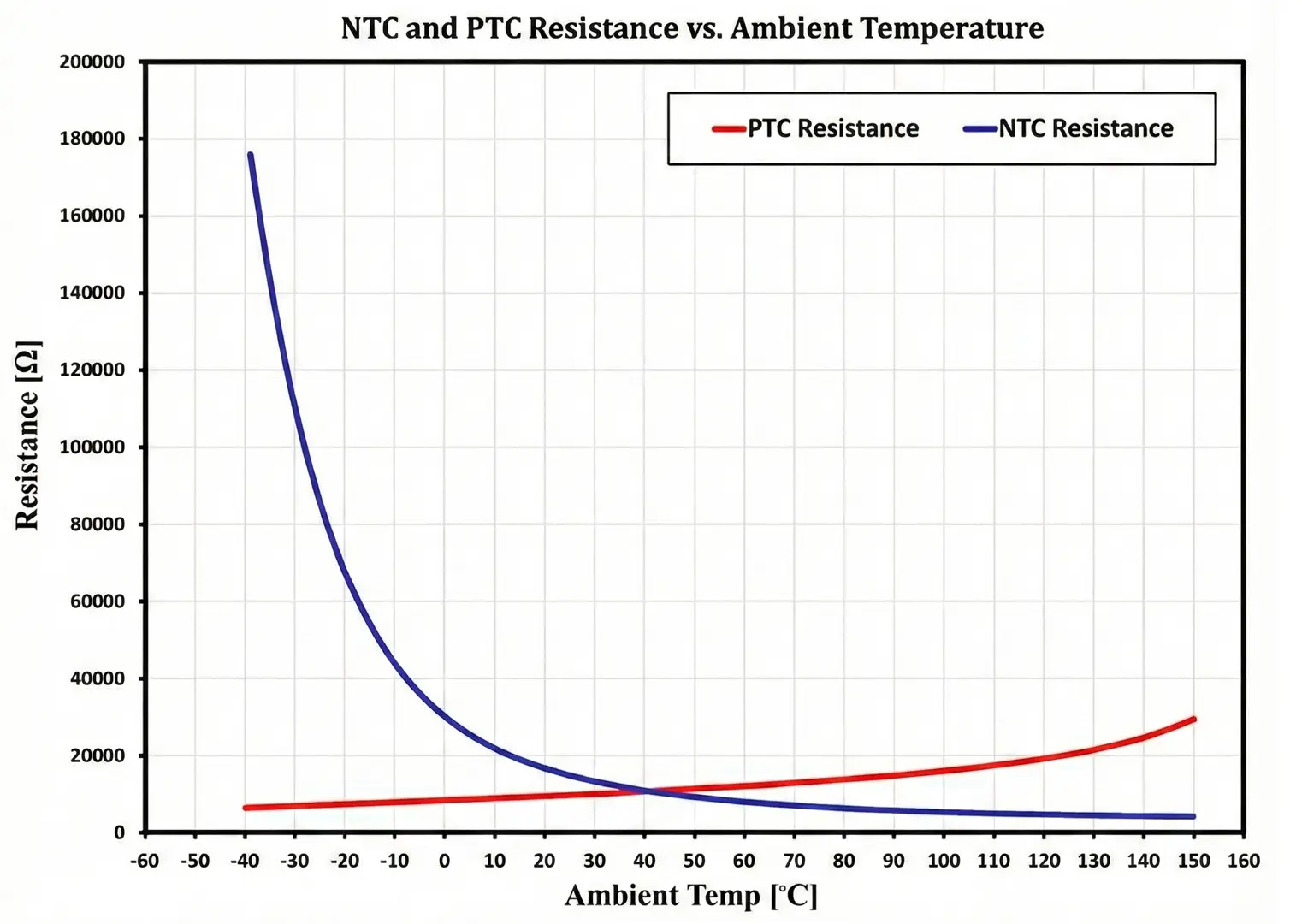
Characteristics of Thermistor
- The NTC curve shows a smooth, continuously decreasing exponential slope.
- The PTC curve shows either a gradual increase (linear type) or a sharp knee at the Curie temperature (switching type).
- The steepness of the slope indicates temperature sensitivity.
- The transition region in PTC thermistors represents the protective operating zone.
- Resistance-Temperature Relationship
- Highly non-linear
- Usually exponential for NTC thermistors
- Temperature Range
- Typical: –55 °C to +300 °C
- Glass-encapsulated types support higher ranges
- Sensitivity
- Much higher than RTDs or thermocouples
- Small temperature changes cause large resistance variation
- Thermal Time Constant
- Time required to reach 63% of final temperature
- Smaller thermistors → faster response
- Power Rating
- Usually low (mW range)
- Excess current can cause self-heating error
Characteristics of NTC Thermistor
An NTC (Negative Temperature Coefficient) thermistor exhibits a decrease in resistance with increasing temperature. The resistance–temperature (R–T) curve is highly nonlinear and follows an exponential decay pattern.
- Negative Temperature Coefficient
- Resistance decreases as temperature increases. dR/dT < 0
- Exponential R–T Relationship
- Resistance drops rapidly at lower temperatures.
- The curve flattens at higher temperatures.
- High Sensitivity
- Small temperature changes produce large resistance variations.
- High temperature coefficient (typically −3% to −6% per °C at 25°C).
- Nonlinear Behavior
- Requires linearization (software or hardware) for precise measurement applications.
- Resistance Range
- Typically from a few ohms to several megaohms at 25°C.
- Thermal Time Constant
- Fast response due to small thermal mass (especially bead types).
- Operating Temperature Range
- Commonly −55°C to +150°C (extended versions available).
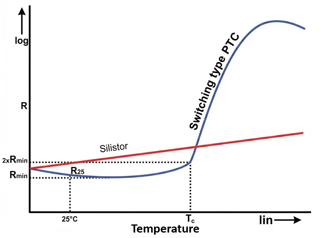
Characteristics of PTC Thermistor
A PTC (Positive Temperature Coefficient) thermistor exhibits an increase in resistance with increasing temperature. Depending on type, the R–T curve may be approximately linear or show a sharp transition.
- X-axis → Temperature (T)
- Y-axis → Resistance (R)
- Curve shows gradual rise at low temperature, followed by a sharp increase at the switching temperature
Thermistors are commonly rated at 25°C (R25), meaning the specified resistance value is measured at 25°C.
- Positive Temperature Coefficient
- Resistance increases as temperature increases. dR/dT > 0
- Switching Behavior (Ceramic PTC)
- At a specific temperature (Curie temperature), resistance increases sharply.
- Can rise by several orders of magnitude within a few degrees.
- Self-Regulating Property
- Increased resistance limits current automatically.
- Enables inherent overcurrent/overtemperature protection.
- Lower Sensitivity (Below Transition)
- Gradual resistance changes before the switching point.
- Resistance Range
- Low resistance at normal temperature.
- Extremely high resistance after transition.
- Thermal Hysteresis
- Cooling curve may not perfectly match heating curve.
- Operating Temperature Range
- Typically −50°C to +150°C (depends on material and design).
How to Read Thermistor Value
Thermistors do not follow standard resistor color codes.
- Nominal Resistance
- Specified as:
- R₍₂₅₎ → resistance at 25 °C
Example: - 10K NTC = 10 kΩ at 25 °C
- R₍₂₅₎ → resistance at 25 °C
- Specified as:
- Beta (β) Value
- Indicates temperature sensitivity:
- Typical β range: 3000 K – 4500 K
- Higher β = higher sensitivity.
- Indicates temperature sensitivity:
- Datasheet Interpretation
- Datasheets provide:
- Resistance vs temperature tables
- R–T curves
- Tolerance (±1%, ±5%, ±10%)
- Datasheets provide:
- Marking Styles
- Printed numeric codes
- Laser-etched codes (SMD)
- Manufacturer-specific identifiers
Selection Criteria for Thermistor
When choosing a thermistor, consider the following parameters carefully:
- Type: NTC or PTC
- Nominal resistance (R25)
- Beta value (β)
- Operating temperature range
- Accuracy and tolerance
- Thermal response time
- Power rating and self-heating
- Physical size and mounting style
- Environmental protection (humidity, chemicals)
- Long-term stability and aging
Advantages of Thermistor
- Very high temperature sensitivity
- Small size and lightweight
- Low cost compared to RTDs
- Fast thermal response
- Simple interface circuitry
- Wide availability in many packages
- Excellent resolution for narrow temperature ranges
Disadvantages of Thermistor
- Highly non-linear characteristics
- Limited temperature range compared to thermocouples
- Self-heating errors under high current
- Requires calibration for precision measurement
- Less stable over long periods than platinum RTDs
Applications of Thermistor
- Temperature Measurement
- Digital thermometers
- Medical temperature probes
- HVAC temperature sensors
- Temperature Control
- Air conditioners
- Refrigerators
- Industrial ovens
- 3D printers
- Inrush Current Limiting
- SMPS input protection
- Power adapters
- LED drivers
- Battery and Power Systems
- Battery packs
- EV battery management systems
- Solar charge controllers
- Protection Circuits
- Overtemperature shutdown
- Motor and transformer protection
- Resettable fuse replacement (PTC)
Thermistor Comparison with RTD and Thermocouple
| Parameter | Thermistor | RTD | Thermocouple |
|---|---|---|---|
| Operating Principal | Semiconductor resistance | Metal resistance | Seebeck voltage |
| Sensitivity | Very High | Moderate | Low |
| Linearity | Poor | Good | Poor |
| Temperature Range | Narrow | Wide | Very Wide |
| Accuracy | High (limited range) | Very High | Moderate |
| Stability | Moderate | Excellent | Good |
| Cost | Low | High | Moderate |
| Power Required | Yes | Yes | No |
| Best For | Medical, electronics | Industrial precision | High-temp, furnaces |
Conclusion
Thermistors are highly sensitive, versatile, and cost-effective temperature-dependent resistors used across almost every domain of electronics. While their non-linear nature requires careful circuit design and calibration, their advantages in sensitivity, size, and response speed make them the preferred choice for many temperature sensing and protection applications. Understanding thermistor types, characteristics, and selection criteria is essential for designing reliable and accurate electronic systems.
Types of Resistors with Symbol, Classification and Applications
What are Passive Electronic Components and their Classification
Light Dependent Resistor (LDR) / Photoresistor Circuit Diagram & Working
