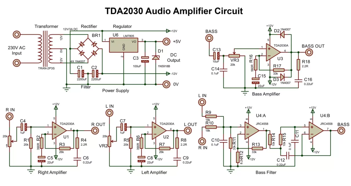
Building a powerful yet compact audio amplifier can greatly enhance your audio experience. This article details how to construct a 3-channel TDA2030 amplifier circuit with separate left, right, and bass channels, powered by a dual ±12V supply. Additionally, it integrates a bass filter circuit, Bluetooth support via a 7805 regulator, and multiple protection features to ensure stability and longevity.
Key Features of TDA2030 Amplifier Circuit
- 3 TDA2030 ICs: Two for stereo channels (left and right) and one for bass amplification.
- Bass Filter Circuit: Filters frequencies below 200Hz for a powerful low-end response.
- 5V Bluetooth Module: Powered using a 7805 voltage regulator.
- Protection Mechanisms: Includes back EMF diodes, Zobel network, and reverse polarity protection.
Component List
| Component | Value/Type | Qty |
|---|---|---|
| TDA2030 IC | Audio amplifier | 3 |
| Diodes | 1N4007 x6, 1N5918B | 7 |
| Resistors | (26kΩ, 20kΩ, 390Ω, 10kΩ, 18kΩ) x2, (33kΩ, 2.2Ω) x3, 8.2kΩ, 560Ω | 18 |
| Potentiometer | 20kΩ | 3 |
| Capacitors | 2200μF x2, 100uF, 0.1μF x3, 0.22μF x4, 22μF x3, 1μF x2, 10μF | 16 |
| LM7805 | 5V Regulator | 1 |
| Transformer | 12-0-12V, 3A | 1 |
TDA2030 Amplifier Circuit Diagram Explained
The TDA2030 amplifier circuit is divided into several sections, each playing a crucial role in delivering high-quality sound. Below, we explain each section in detail.
1. Power Supply Section
Components
- Transformer: 12-0-12V, 3A
- Diodes: 4x 1N4007 (bridge rectifier)
- Filter Capacitors: 2x 2200μF/25V
- Voltage Divider: Creates ±12V from 24V DC
- LM7805 IC: 5V regulator for Bluetooth
- Capacitor: 100μF (stabilizes output)
- Zener Diode: 1N5918B

Working
- The 12-0-12V transformer converts AC mains to 24V DC.
- The bridge rectifier (1N4007 diodes) rectifies AC into DC.
- Two 2200μF capacitors stabilize the ±12V power rails.
- The 7805 voltage regulator converts +12V to +5V, powering the Bluetooth module.
2. Stereo Amplification (Left/Right Channels)
Components per Channel
- TDA2030 IC
- Feedback Network: 26kΩ + 390Ω resistors (sets gain), 22μF capacitor at the inverting pin.
- DC Blocking: 1μF capacitor at input with 20kΩ resistor to ground.
- Zobel Network: 2.2Ω + 0.22μF capacitor at speaker output.

Working
- Feedback Control: The 26kΩ resistor sets volume, while the 390Ω resistor stabilizes gain. Increasing it to 47kΩ boosts output.
- Output Protection: The Zobel network (2.2Ω + 0.22μF) reduces high-frequency noise.
- Diode Protection: Two 1N4007 diodes protect against speaker back EMF.
TDA2030 Mono Amplifier Circuit
Here is a single channel amplifier with diode protection at output. You can use it if you want a sample and low power design and don’t want any bass or stereo output.
3. Bass Filter Circuit
Components
- Resistors: 18kΩ x2, 33kΩ x2, 10kΩ x2, 8.2kΩ
- Capacitors: 0.1μF (104) x2, 0.22μF (224) x1
- Preamp Stage: JRC4558 Op-Amp
Working
- The first op amp makes a preamplifier circuit with 33kΩ and 8.2kΩ resistors defining the gain of amplifier.
- The RC filter (two 10kΩ + 0.1μF + 0.22uF and second op amp of 4558 IC makes a low pass filter) blocks frequencies above 200Hz, isolating the bass signal.
- The filtered bass signal is then sent to the TDA2030 bass channel for amplification.
4. Bass Amplifier Circuit
Components
- TDA2030 IC
- Input: Filtered bass signal from 4558 op-amp.
- Feedback Network: 33kΩ + 560Ω resistors (sets gain), 22μF capacitor at inverting.
- DC Blocking: 10μF capacitor at input.
- Zobel Network: 2.2Ω + 0.22μF capacitor at speaker output.
- Diode Protection: Two 1N4007 diodes protect against back EMF from speakers.

Bass Volume Control
- A 50kΩ potentiometer can be added in the feedback loop (with the 26kΩ resistor) for adjustable bass boost.
5. Bluetooth Module Integration
Components
- 7805 Regulator: Provides stable +5V.
- Decoupling Capacitor: 100μF/16V.
Connection
- +5V powers the Bluetooth module.
- Audio Out from Bluetooth connects to the amplifier inputs.
PCB Layout Tips and Troubleshooting Guide
- Star Grounding: Connect all grounds to a single point (transformer’s center tap).
- Isolation: Keep input/output paths separate to avoid noise.
- Heat Sinks: Attach heat sinks to all TDA2030 ICs to prevent overheating.
- Test each channel separately before final assembly for best results.
| Issue | Solution |
|---|---|
| Distorted Bass | Replace the 0.1μF capacitor in bass filter. |
| Humming Noise | Verify ground connections. Increase filter capacitor values. |
| Overheating | Add larger heat sinks. Check speaker impedance (4Ω-8Ω). |
Modifications to TDA2030 Amplifier Circuit
Adjustable Bass Boost
- Replace the two 10kΩ resistor with a dual 50kΩ potentiometer.
Bridge Mode for More Power
- Use two TDA2030 ICs per channel for an output of 28W.

Conclusion
This TDA2030-based amplifier delivers crisp stereo sound and powerful bass, making it a great DIY project. Follow the circuit design carefully when you will make it, and you’ll have a high-performance amplifier for your audio system.


