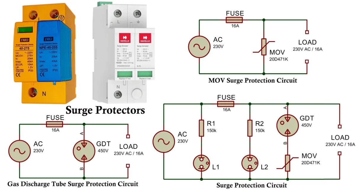
A surge protector is an electronic protection device designed to safeguard electrical and electronic equipment from voltage surges (transient overvoltage). A voltage surge is a sudden and short-duration spike in voltage that exceeds the normal operating voltage of a system. These surges may last from a few nanoseconds to milliseconds but can reach several kilovolts in magnitude.
Surges are commonly caused by:
- Lightning strikes (direct or nearby)
- Switching of heavy inductive loads
- Faults in power distribution lines
- Sudden power restoration after an outage
- Electrostatic discharge (ESD)
Sensitive electronic devices such as microcontrollers, computers, communication equipment, medical electronics, industrial control systems, and power supplies can be permanently damaged by even a single high-energy surge. A surge protector limits the voltage supplied to a load by clamping, diverting, or absorbing excess energy, thus preventing damage.
Surge Protector Circuit Diagram
1. MOV-Based Surge Protector Circuit
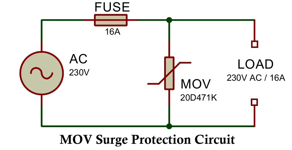
Components
- MOV (Metal Oxide Varistor)
- Non-linear resistor that clamps excessive voltage.
- Absorbs transient energy and protects the load.
- Fuse
- Disconnects the circuit if the MOV fails short or overheats.
- Thermal fuse (optional)
- Mounted close to the MOV to prevent thermal runaway and fire risk.
- EMI filter (optional)
- Suppresses high-frequency noise and switching transients.
Working of Surge Protector
- During normal operation the MOV presents high impedance.
- When voltage exceeds the MOV’s clamping voltage (e.g., 470V peak),
- The MOV’s resistance drops sharply to a very low value.
- The MOV conducts heavily and diverts the surge current to neutral or earth.
- The load voltage is clamped to a safe level.
- Once voltage returns to normal, MOV resistance increases again.
- Normal operation resumes.
2. Gas Discharge Tube (GDT) Based Surge Protector Circuit
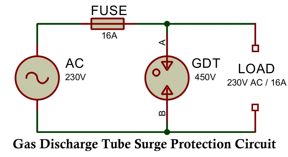
Components
- GDT (Gas Discharge Tube)
- Normally open circuit.
- Ionizes and becomes conductive when breakdown voltage is exceeded.
- Fuse
- Protects wiring and isolates the circuit if the GDT remains latched.
- Series resistor or PTC (optional)
- Limits follow-on current after GDT conduction.
- EMI filter (optional)
- Suppresses fast, high-frequency spikes.
Working of Surge Protector
- The GDT does nothing during normal operation.
- During a high-energy surge, the gas ionizes and forms a low-impedance path.
- The surge current is shunted safely away from the load.
Key characteristics
- Handles very large surge currents (kiloamp range).
- Slower response time than MOVs (microseconds).
- Very long service life for repeated high-energy events.
3. Surge Protection Circuit with GDT and MOV
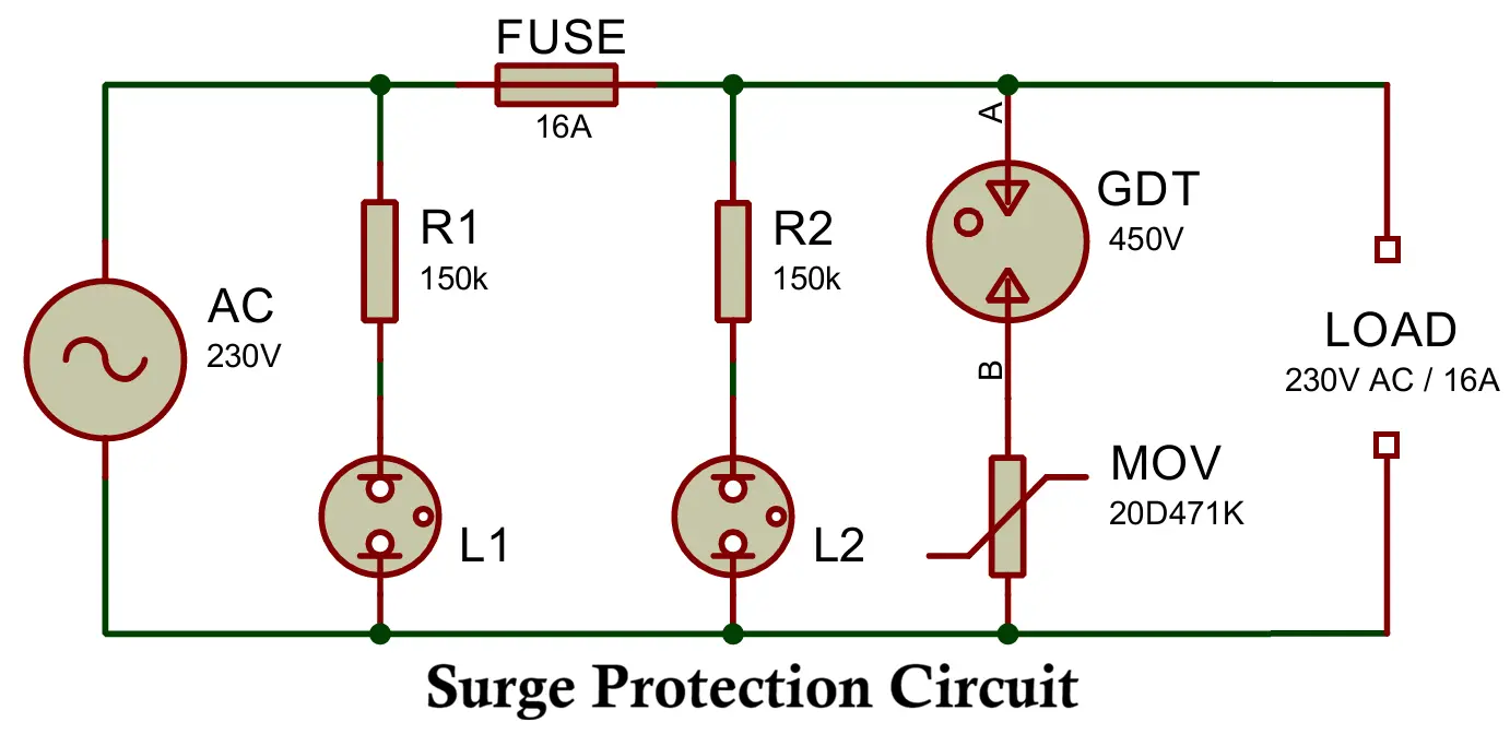
Components
- Neon Bulb L1 (Before Fuse – Power Indicator)
- Indicates that mains voltage is present at the input.
- Goes dark if the supply is absent.
- Neon Bulb L2 (After Fuse – Fuse Status Indicator)
- Indicates that the fuse is intact and power is reaching the load.
- Turns off if the fuse is blown while input power is still present.
- Fuse
- Isolates the circuit if the MOV or GDT fails short or overheats.
- MOV
- Fast-acting clamp for high-speed transients.
- GDT
- High-energy crowbar for lightning-class surges.
- EMI filter (optional)
- Suppresses conducted interference.
Working of Surge Protector
- The MOV responds first to fast voltage spikes and clamps them quickly.
- The GDT fires during large, high-energy surges and carries most of the current.
- The fuse disconnects the circuit if either device fails short.
- The EMI filter reduces conducted noise and ringing.
Benefits of using both devices
- Fast response to short transients (MOV).
- High surge-energy capability (GDT).
- Reduced stress and heating of the MOV.
- Increased overall reliability and lifetime.
Typical Component Guidelines
- MOV
- 14D471K or 20D471K (approx. 470 V clamping).
- GDT
- 230–350 V DC breakdown voltage.
- Fuse
- Time-delay type rated slightly above nominal line current.
- Thermal fuse
- 115–130 °C trip temperature.
- EMI filter
- Common-mode choke with X/Y capacitors rated for mains use.
- Each neon lamp
- series current-limiting resistor (typically 150 kΩ–330 kΩ for 230 VAC).
- Resistors must be mains-rated and flame-retardant.
- Neon indicators should be rated ≥250 VAC continuous.
Types of Surge Protectors
Surge protectors (SPDs Surge Protective Devices) are classified according to:
- The technology they use to divert or clamp surges,
- The location where they are installed in the electrical system,
- The electrical paths they protect.
1. Based on Protection Technology
This classification describes how the SPD limits overvoltage.
1.1 Metal Oxide Varistor (MOV) Based
- Non-linear voltage-dependent resistor.
- Remains high impedance at normal voltage.
- Becomes low impedance when voltage exceeds its clamping threshold.
Characteristics
- Very fast response time (nanosecond range).
- Moderate surge energy capability.
- Gradually degrades with each surge event.
- Failure mode is usually short circuit if overstressed.
Typical applications
- AC mains protection.
- Type 2 and Type 3 SPDs.
- Power strips and distribution boards.
1.2 Gas Discharge Tube (GDT) Based
- Uses ionized gas between electrodes to conduct surge current.
- Acts as a “crowbar” device once breakdown voltage is reached.
Characteristics
- Very high surge current capability (kA range).
- Slower response time (microsecond range).
- Very long operational life.
- Higher residual voltage than MOVs.
Typical applications
- Lightning protection.
- Telecom lines and service entrances.
- Type 1 SPDs.
- Often combined with MOVs for coordinated protection.
1.3 Transient Voltage Suppression (TVS) Diodes
- Semiconductor device designed for fast transient clamping.
- Conducts sharply when breakdown voltage is exceeded.
Characteristics
- Extremely fast response time (< 1 ns).
- Precise and stable clamping voltage.
- Low energy handling capability.
Typical applications
- Data lines (USB, Ethernet, HDMI).
- Low-voltage DC power rails.
- Sensitive electronics.
1.4 Zener Diode Based
- Operates in reverse breakdown region to regulate voltage.
Characteristics
- Simple and low cost.
- Suitable only for low-energy transients.
- Lower power handling than TVS diodes.
Typical applications
- Small DC circuits.
- Microcontroller and sensor inputs.
2. Based on Installation Level (IEC Classification)
This classification defines where the SPD is installed and what level of surge energy it must withstand.
Type-1: Service Entrance Protection
- Installed at the building service entrance or main panel.
- Protects against:
- Direct lightning strikes,
- High-energy external surges from the utility network.
- Very high current ratings (tens of kiloamps).
- Usually implemented with GDTs or spark gaps.
Type-2: Distribution Board Protection
- Installed in sub-panels and internal distribution boards.
- Protects against:
- Switching surges,
- Induced lightning effects,
- Residual surges from Type 1 devices.
- Moderate current ratings.
- Usually implemented with MOV or hybrid devices.
Type-3: Point-of-Use Protection
- Installed close to the equipment being protected.
- Protects against low-energy, fast transients.
- Very fast response.
- Often integrated into power strips and equipment power supplies.
Installation Level Summary
- Type 1 blocks large external surges.
- Type 2 limits internal distribution surges.
- Type 3 protects individual devices.
They are intended to work together in a cascaded system, not as alternatives.
3. Based on Mode of Protection
This classification defines which electrical conductor pairs are protected.
Line-to-Neutral (L–N)
- Protects against differential-mode surges.
- Prevents excessive voltage across the load.
Line-to-Earth (L–E)
- Diverts common-mode surges safely to earth.
- Essential for lightning and insulation protection.
Neutral-to-Earth (N–E)
- Prevents the neutral from rising above earth potential.
- Protects grounded equipment and communication interfaces.
High-End SPD
- Provides protection on all three paths: L–N, L–E, N–E.
- Combines multiple technologies (e.g., GDT + MOV + TVS).
- Be installed in a cascaded Type 1 → Type 2 → Type 3 structure.
Advantages of Surge Protectors
- Protect sensitive electronic equipment from damage caused by voltage surges.
- Reduce equipment downtime and maintenance costs.
- Improve system reliability and service continuity.
- Limit insulation stress and reduce the risk of fire and electric shock.
- Provide fast response to transient overvoltages.
- Can be coordinated in layers (Type 1, Type 2, Type 3) for comprehensive protection.
- Extend the operational life of connected equipment.
- Improve compliance with electrical safety and EMC standards.
Disadvantages of Surge Protectors
- Do not protect against sustained overvoltage or undervoltage conditions.
- Effectiveness depends on proper installation and earthing.
- Protection devices degrade over time and may require periodic replacement.
- Low-quality SPDs may fail short and cause nuisance tripping or fuse blowing.
- Cannot protect against direct lightning strikes to the equipment itself.
- Additional cost in system design and installation.
- Poor coordination between protection stages can reduce effectiveness.
Applications of Surge Protectors
Residential
- Protection of home appliances (TVs, refrigerators, washing machines).
- Protection of home automation systems and routers.
- Plug-in surge protectors for computers and entertainment systems.
Commercial
- Protection of office equipment, servers, and network infrastructure.
- Protection of building automation and access control systems.
- Installation in distribution panels for building-wide protection.
Industrial
- Protection of PLCs, drives, sensors, and control systems.
- Protection of industrial communication networks.
- Protection of power electronics and motor drives.
Telecommunications and IT
- Protection of telephone, Ethernet, and data lines.
- Protection of base stations, routers, and switching equipment.
- Protection of PoE and RF systems.
Renewable Energy Systems
- Protection of photovoltaic inverters and DC strings.
- Protection of wind turbine control and power electronics.
- Protection of battery storage systems.
Transportation and Infrastructure
- Protection of railway signaling and control systems.
- Protection of traffic control systems.
- Protection of water treatment and pumping stations.
Surge Protection vs Overvoltage Protection
| Parameter | Surge Protector | Overvoltage Protection |
|---|---|---|
| Protects against | Transient spikes | Long-duration high voltage |
| Response time | Very fast (ns–µs) | Slower |
| Energy level | High peak, short duration | Lower peak, long duration |
| Typical devices | MOV, GDT, TVS | Relays, crowbar, OV detectors |
Conclusion
A surge protector is an essential protective device in modern electrical and electronic systems. It prevents transient overvoltage from damaging sensitive equipment by rapidly clamping or diverting excess energy. With the increasing penetration of electronics in homes, industries, renewable energy systems, and communication infrastructure, surge protection has become not only recommended but mandatory for safety, reliability, and compliance with international standards.
Proper selection of surge protection devices based on voltage rating, surge current rating, response time, and installation location ensures effective and long-term protection of critical assets.
Difference Between Surge Protection and Over Voltage Protection
3 Simple IR Proximity Sensor Circuits with Working & Applications
