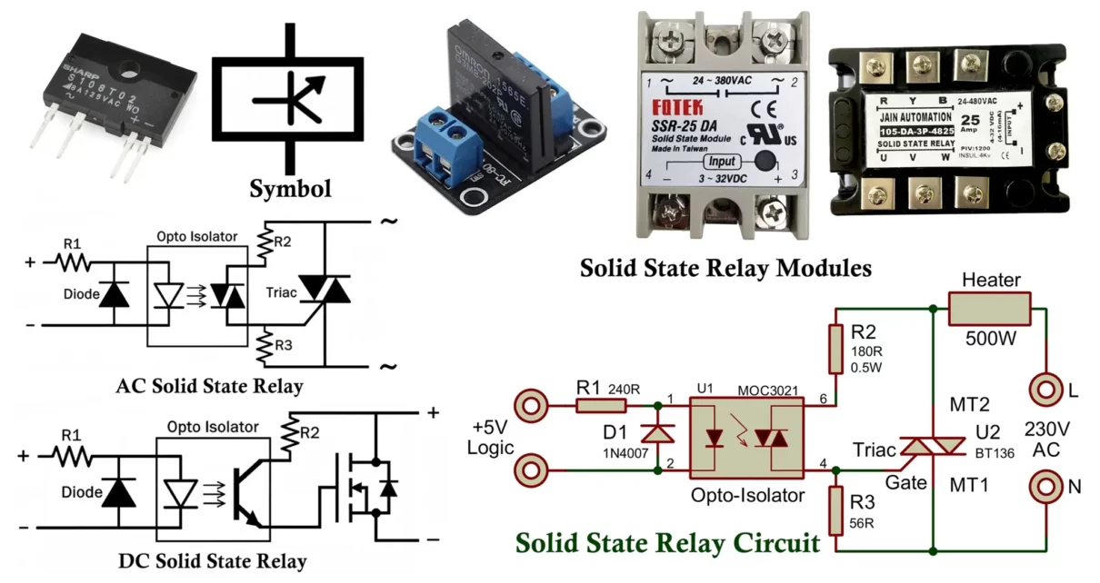
A Solid-State Relay (SSR) is an electronic switching device that performs the same function as an electromechanical relay (EMR) but without any moving parts. Instead of mechanical contacts, it uses semiconductor devices such as thyristors, Triacs, MOSFETs, or transistors to switch electrical loads ON or OFF.
Because there are no moving parts, SSRs offer longer life, silent operation, high-speed switching, and immunity to vibration and shock—making them ideal for modern automation and control systems.
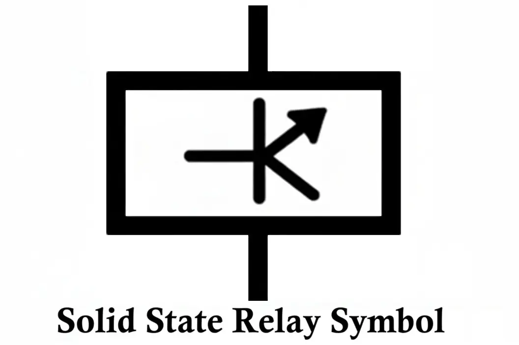
Symbol of Solid State Relay
The symbol of a solid-state relay is different from an electromechanical relay due to semiconductor switching components instead of mechanical contacts.
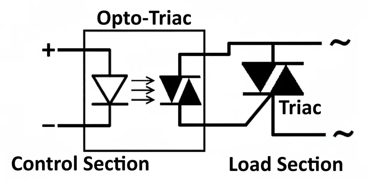
Construction of Solid State Relay
An SSR consists of three main sections:
- The input side (left) consists of a LED that acts as the optical trigger.
- The output side (right) consists of semiconductor switches like triac, thyristor pair, or MOSFET.
- The optical isolation barrier ensures electrical separation between input and output.
1. Input Circuit (Control Side)
- The input circuit is similar to the coil in an electromechanical relay.
- It typically contains a Light Emitting Diode (LED) which emits infrared light when a small DC control voltage is applied.
- The LED is optically coupled to the output circuit through a photodetector.
Key features:
- Input voltage range: 3–32V DC (commonly used in control systems)
- Current consumption: Typically 5–20mA
- Optical coupling provides galvanic isolation (usually >2.5kV)
2. Isolation (Coupling) Stage
- This stage provides optical isolation between input and output.
- It uses an optocoupler—a combination of LED and a photosensitive device (such as a photodiode, phototransistor, or phototriac).
- The light from the LED activates the output device, eliminating any electrical connection between the control and load circuits.
Purpose:
- Prevents high voltages or current spikes from feeding back to the control circuitry.
- Ensures safety and system reliability.
What Are Optoisolators and Optocouplers, How Do They Work?
Optocoupler / Optoisolator – Construction, Working, Types & Applications
Electromechanical Relay – Symbol, Construction, Working and Types
3. Output Circuit (Switching Side)
- The output stage performs the actual switching of the load.
- It can use different semiconductor devices depending on the load type:
- Triac or SCRs – for AC loads
- MOSFET or Transistor – for DC loads
- A snubber circuit (RC network) is often included to protect against voltage spikes and transient surges.
Typical components:
- Optically triggered Triac or SCR pair for AC
- Power MOSFET pair for DC
- Diode or snubber for transient protection
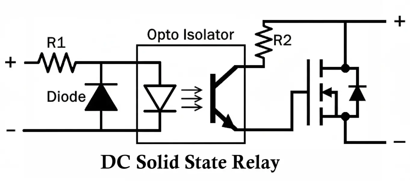
Circuit Diagram of Solid State Relay

- When the input control voltage is applied, the LED inside the optocoupler emits light.
- The phototriac inside the optocoupler gets triggered, which in turn triggers the main power Triac.
- The load (AC motor, lamp, or heater) is then connected to the AC supply through the Triac.
- When the input control is removed, the Triac stops conducting at the next zero-crossing point, turning off the load.
Working Principle of Solid State Relay
The working of an SSR is based on optical coupling and semiconductor switching. Here is a step-by-step working:
- Input Activation:
- A small DC control voltage (e.g., 5V or 12V) is applied to the input terminals.
- This current flows through the LED in the optocoupler, causing it to emit infrared light.
- Optical Coupling:
- The emitted light is detected by a photosensitive device (like a photodiode or phototriac) in the output section.
- Since the coupling is optical, there’s no electrical connection between control and load sides.
- Output Switching:
- The photodetector triggers the semiconductor switch (Triac, SCR, or MOSFET), allowing the load current to flow.
- When the input signal is removed, the light goes off, and the output device stops conducting.
- Special Feature (for AC SSRs):
- Many SSRs include zero-cross or peak detection circuits that ensure switching occurs only at certain part of AC voltage.
- This minimizes electrical noise and inrush current, improving device life.
Types of Solid State Relays
SSRs are categorized based on load type, switching mode, and output device.
1. AC Solid State Relays
AC SSRs are designed to control AC loads (typically from 24 V AC up to 480 V AC or more).
They use thyristors (SCRs) or triacs as the main output switching elements.
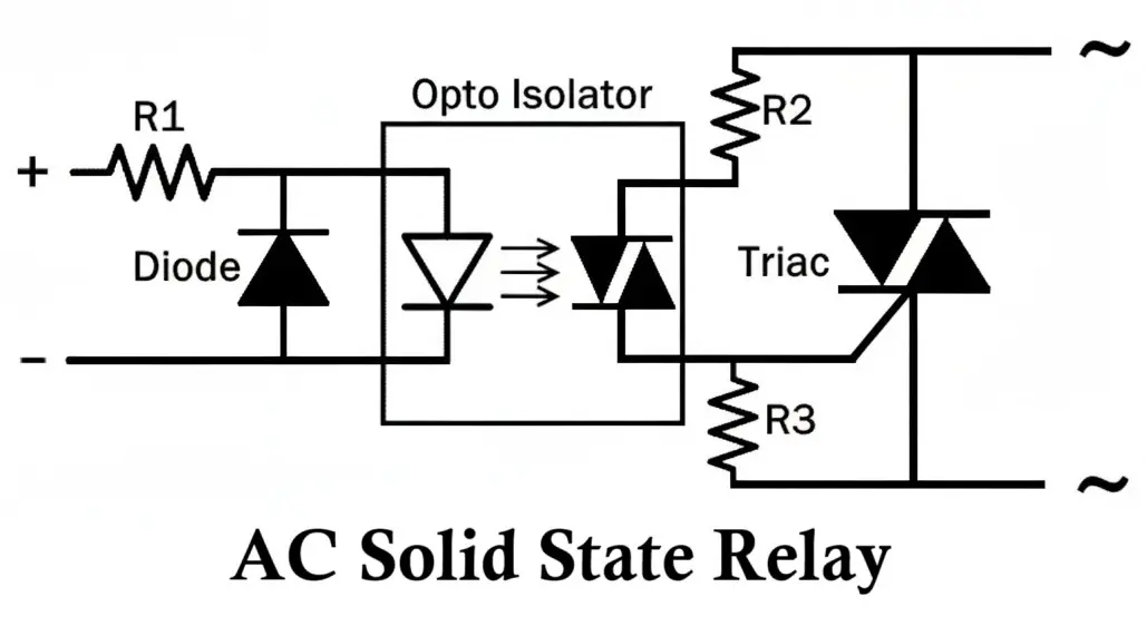
Internal Structure:
- Input Stage: Accepts a control signal (DC or AC), often driving an LED within an optocoupler.
- Isolation Stage: Provides galvanic separation via an optical isolator or optotriac.
- Output Stage: Uses anti-parallel SCRs or a triac to handle the AC load.
1.1 Zero-Crossing AC SSR
Working Principle:
This relay waits until the AC waveform crosses zero volts before switching on.
When the control input is applied, the LED inside the optocoupler activates and triggers the optotriac, which in turn triggers the main triac/SCR pair at the next zero-cross point.
Switch-off occurs automatically when the current falls to zero in the AC cycle.
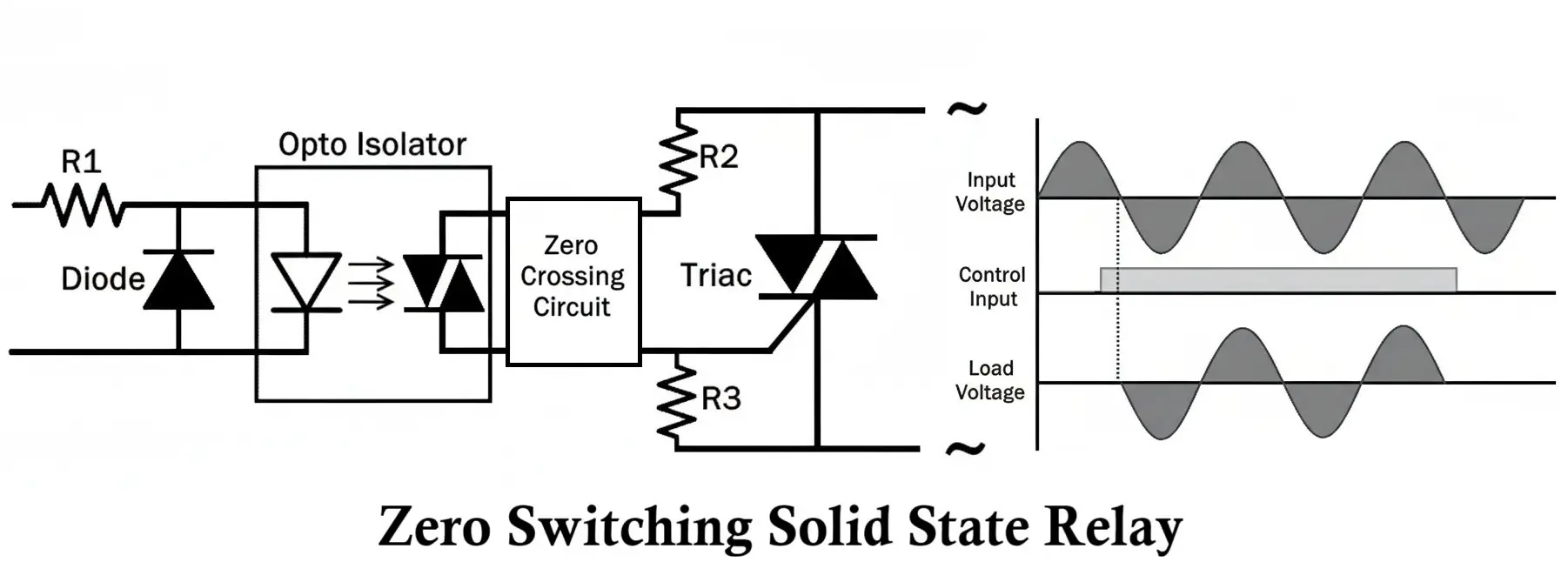
Characteristics:
- Turn-on delay up to one half-cycle (8.3 ms for 60 Hz).
- Turn-off occurs naturally at current zero.
- Minimal electrical noise and reduced surge current.
Advantages:
- Low electromagnetic interference (EMI)
- Smooth switching of resistive loads
- Less stress on connected equipment
Limitations:
- Not suitable for phase-angle control (dimming or motor speed control)
- Slight response delay due to zero-cross synchronization
Applications:
- Resistive heaters
- Incandescent lamps
- Ovens
- Industrial temperature control systems
1.2 Random Turn-On (Instant-On) AC SSR
Working Principle:
This type turns on immediately when the control signal is applied, regardless of the AC waveform phase.
The triac or SCR conducts instantly, allowing fast response switching.
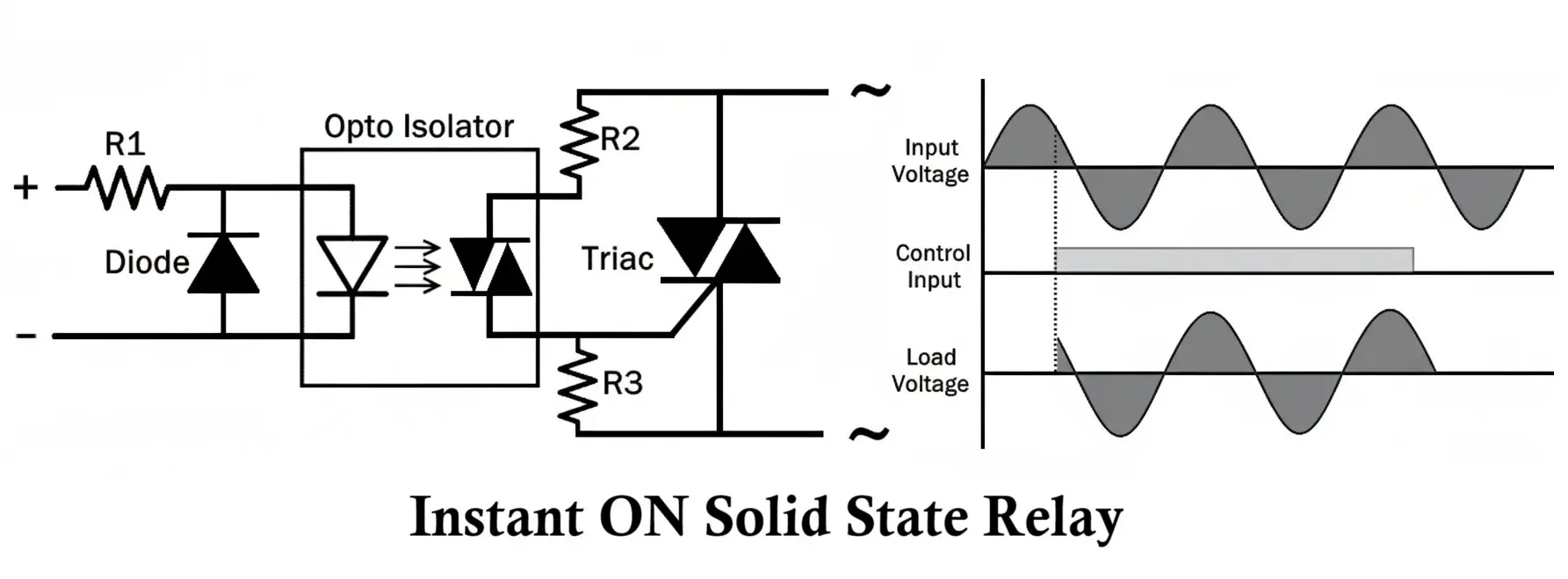
Advantages:
- Very fast switching (typically <100 µs)
- Suitable for phase-angle or burst-fire control
- Works well with inductive or dynamic loads
Limitations:
- Generates more electrical noise due to high-voltage switching
- Often requires RC snubbers or filters to suppress transients
Applications:
- AC motor control
- Light dimming
- Inductive load switching
- Power regulators
1.3 Peak Switching AC SSR
Working Principle:
Switches on when the AC voltage reaches its peak value.
Used for applications requiring controlled switching at the maximum voltage point for improved load control or energy management.
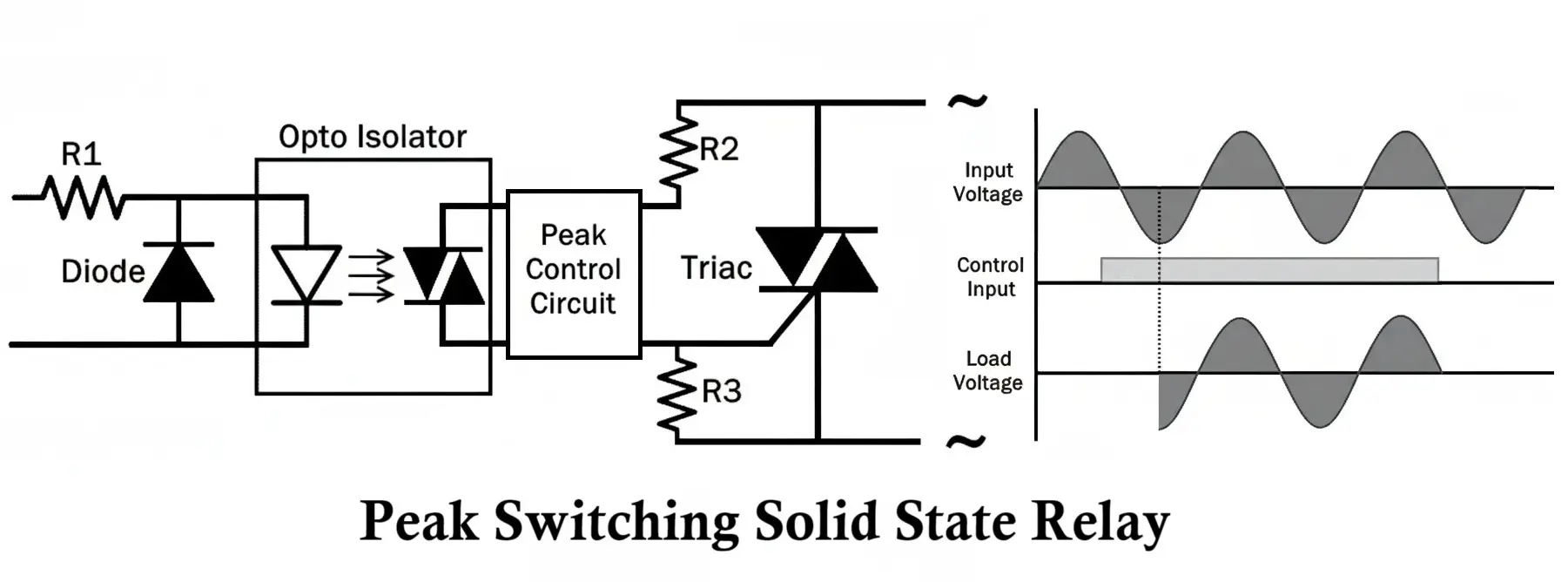
Applications:
- Specialized AC power conditioning
- Laboratory or research power control systems
1.4 Analog-Controlled AC SSR (Phase Angle or Burst Fire Control)
Working Principle:
Instead of a simple ON/OFF input, the control signal is analog (for example, 0–10 V DC or 4–20 mA).
The relay modulates the conduction angle within each AC half-cycle (phase control) or turns full AC cycles on and off in rapid succession (burst fire control) to regulate the average power delivered to the load.
Applications:
- Proportional temperature control in heating systems
- Industrial light dimming
- Process control systems using PID loops
2. DC Solid State Relays
DC SSRs are designed to switch direct current loads.
Because DC current does not have a natural zero-crossing point, DC SSRs require active control to turn off the output.
Internal Structure:
- Input Stage: Usually contains an optocoupler LED for signal isolation.
- Output Stage: Uses MOSFETs, IGBTs, or bipolar transistors (often arranged in pairs for polarity handling).
2.1 MOSFET-Based DC SSR
Working Principle:
When the control input LED is energized, it activates a photo-transistor or photo-MOSFET that drives the gate of a power MOSFET (or a pair of MOSFETs in series for bidirectional operation).
Switching times are extremely fast—often in microseconds.
Characteristics:
- Low ON resistance (Rds_on)
- Low heat generation
- Efficient at low and medium DC voltages (typically up to 200 V DC)
Advantages:
- Fast response and low power loss
- No arcing or contact wear
- Compact and reliable
Limitations:
- Limited voltage handling compared to IGBT-based designs
- Needs flyback diodes or transient suppressors for inductive loads
Applications:
- Battery load switching
- DC solenoid or valve control
- Robotics and automation
- PLC control outputs
2.2 IGBT-Based DC SSR
Working Principle:
The input LED activates a gate driver circuit that triggers an Insulated Gate Bipolar Transistor (IGBT).
The IGBT then conducts and allows large DC currents to pass through.
Characteristics:
- Designed for high-voltage, high-current DC circuits
- Combines the advantages of MOSFET control and bipolar transistor power capability
Advantages:
- Capable of switching several hundred amps and kilovolts
- Efficient and reliable for DC power control
Limitations:
- More expensive than MOSFET-based SSRs
- Requires careful thermal management (heat sinks)
Applications:
- DC motor drives
- Electric vehicle power circuits
- Renewable energy systems (solar, battery)
- High-voltage DC contactors
2.3 Transistor-Based DC SSR
Working Principle:
Uses bipolar junction transistors (BJTs) or Darlington pairs as the output device.
These are typically used in low-power DC circuits for cost efficiency.
Applications:
- Instrumentation
- Logic-level switching
- Signal control in low-current DC circuits
Comparison of AC and DC Solid State Relay
| Feature | AC SSR | DC SSR |
|---|---|---|
| Output Device | Triac / SCR | MOSFET / IGBT |
| Load Type | AC | DC |
| Turn-off Mechanism | Natural current zero | Active turn-off |
| Typical Voltage Range | 24–480 V AC | 5–1000 V DC |
| Ideal Load | Resistive, Inductive (AC) | DC motors, solenoids |
| Isolation | Optocoupler | Optocoupler |
| Primary Advantage | Noise-free AC switching | High-speed DC control |
Classification of Solid State Relays
Here are short summary tables for classification of all types of solid-state relays.
Based on Load Type:
| Type | Output Device | Used For | Example |
|---|---|---|---|
| AC SSR | Triac or SCR pair | AC loads | Heater, motor, lamp |
| DC SSR | MOSFET or Transistor | DC loads | Solenoid, LED, DC motor |
SSR Types by Switching Method:
| Type | Description | Advantage |
|---|---|---|
| Zero Switching SSR | Switches ON when the AC voltage crosses zero. | Reduces transients and noise. |
| Peak Switching SSR | Switches ON when the AC voltage crosses its peak. | Reducing inrush current surge. |
| Random Turn-On SSR | Switches ON immediately when control signal is applied. | Suitable for phase-control applications. |
| Analog SSR | Provides variable output proportional to input control voltage. | Used for proportional control systems (e.g., temperature). |
Based on Coupling Device:
| Type | Coupler Used | Application |
|---|---|---|
| Opto-Triac coupled | MOC3021, MOC3063 | AC switching |
| Opto-SCR coupled | MOC3010, MOC3011 | High current AC control |
| Opto-MOSFET coupled | TLP222A | Low voltage DC control |
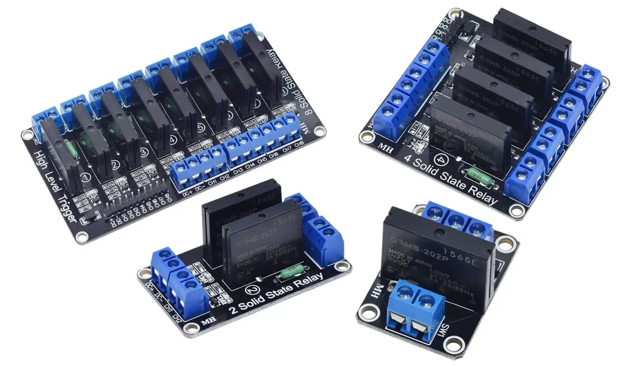
SSR Types by Polarity and Configuration
| Type | Description | Common Application |
|---|---|---|
| Single Pole Single Throw (SPST) | One input controls one output circuit; basic ON/OFF function | General-purpose switching |
| Double Pole Single Throw (DPST) | Simultaneous control of two circuits (often two AC phases) | Dual-phase control systems |
| Single Pole Double Throw (SPDT) | Switches between two output paths (rare in SSRs) | Signal routing |
| Multi-channel SSR | Multiple SSR circuits in one module, independently controlled | PLC and industrial automation systems |
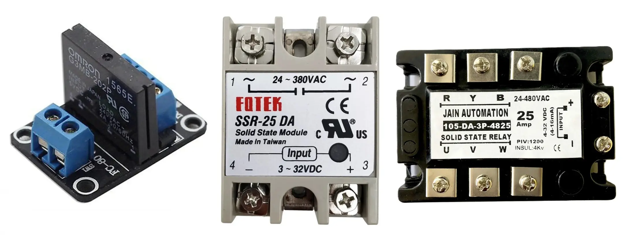
Mounting Configurations of SSR
| Type | Description | Typical Use |
|---|---|---|
| Panel Mount SSR | Bolted onto a heat sink for cooling | High-current loads |
| DIN Rail Mount SSR | Clips onto industrial DIN rails | Control panels and automation |
| PCB Mount SSR | Soldered directly on circuit boards | Compact, low-power circuits |
| Socket Mount SSR | Pluggable design for easy replacement | Maintenance-heavy applications |
Design Considerations
- Heat Dissipation: SSRs produce heat; use proper heat sinks and check derating curves.
- Leakage Current: A small off-state current always flows; sensitive circuits must account for this.
- Snubber Circuits: Use for inductive loads to suppress voltage spikes.
- Input Drive: Match control signal levels with the SSR’s input trigger requirements.
- Overvoltage Protection: Use MOVs or TVS diodes to protect from transient surges.
Advantages of Solid State Relay
- No Moving Parts:
Ensures silent, vibration-free, and long-life operation. - High Switching Speed:
Can switch in microseconds – ideal for automation and high-speed control. - Electrical Isolation:
Complete galvanic isolation between input and output via optical coupling. - No Contact Arcing:
Prevents wear and tear, unlike mechanical relays. - Low Power Control Signal:
Requires only a few milliamperes to operate. - Shock and Vibration Resistant:
Highly durable in harsh environments. - Zero-Cross Switching Option:
Reduces electrical noise and transients in AC applications. - Compact and Lightweight Design:
Ideal for space-constrained electronic systems.
Disadvantages of Solid State Relay
- Higher Cost:
More expensive than electromechanical relays. - Leakage Current:
Even in the OFF state, a small current flows through the semiconductor device. - Limited Overload Capacity:
Sensitive to surge currents and overvoltage. - Heat Dissipation Required:
Generates heat during operation; may need a heat sink. - Polarity Sensitive (for DC SSRs):
Must be connected correctly according to polarity. - No Overload Protection:
External protection circuits are often required.
Applications of Solid State Relay
- Industrial Automation:
For controlling motors, heaters, and solenoids. - Temperature Control Systems:
Used with PID controllers for heating elements. - Home Appliances:
Found in microwave ovens, induction cookers, and washing machines. - Lighting Control:
For dimming or switching high-power lamps silently. - PLC and Microcontroller Interfaces:
For controlling AC/DC loads with low voltage logic signals. - HVAC Systems:
To control compressors, fans, and blowers. - Medical Equipment:
For noise-free switching in sensitive electronic devices. - Test and Measurement Instruments:
For precise, rapid switching of circuits. - Renewable Energy Systems:
Used in solar inverters and battery management systems for isolation and control.
Typical Applications by SSR Type
| Application | SSR Type | Example |
|---|---|---|
| Heater control | Zero-cross AC SSR | Industrial oven |
| Light dimming | Phase-angle AC SSR | Stage lighting |
| DC motor control | MOSFET DC SSR | Robotic drive system |
| Battery switching | IGBT DC SSR | Electric vehicle systems |
| Temperature control | Analog SSR | PID-based heating control |
| PLC automation | Multi-channel SSR | Factory control modules |
Solid State Relay and Electromechanical Relay Differences
| Feature | Solid State Relay | Electromechanical Relay |
|---|---|---|
| Switching Element | Semiconductor devices | Mechanical contacts |
| Moving Parts | None | Present |
| Switching Speed | Very high (µs range) | Slow (ms range) |
| Life Span | Very long | Limited (mechanical wear) |
| Noise | Silent | Audible clicking sound |
| Isolation | Optical | Magnetic |
| Leakage Current | Yes (small) | No |
| Overload Capacity | Limited | High |
| Cost | Higher | Lower |
Conclusion
The Solid State Relay (SSR) represents a significant advancement over traditional electromechanical relays by offering silent, high-speed, and long-life switching without mechanical wear. Its optical isolation, compact design, and high reliability make it an essential component in industrial automation, temperature control, and precision electronic systems.
However, engineers must consider its leakage current, heat dissipation, and cost while designing circuits. When used correctly, SSRs provide superior performance, especially where silent, reliable, and high-speed operation is critical.
Electromechanical Relay – Symbol, Construction, Working, Types and Applications
What is a Sensor? Types of Sensors, Classification & Applications
TRIAC Full Form, Symbol, Working, VI Characteristic & Application
What is Silicon Controlled Rectifier? (SCR) Construction, Working & Applications
Types of Transistors: Classification (BJT, JFET, MOSFET & IGBT)
Photocoupler (Optocoupler / Optoisolator) – Construction, Working, Types & Applications
