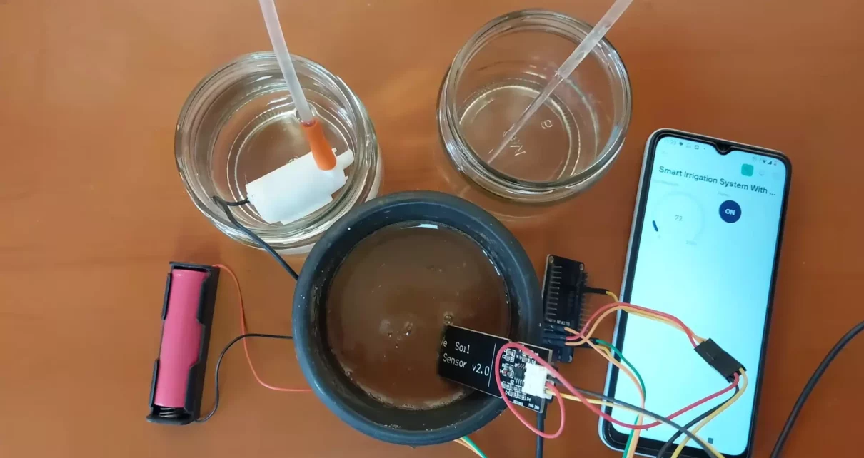
With water scarcity becoming a global concern and agriculture demanding optimal water usage, smart irrigation systems have emerged as a sustainable solution. This article presents a Smart IoT-Based Automatic Irrigation System built using an ESP32 microcontroller, soil moisture sensor, water pump, and Blynk IoT platform for real-time monitoring and control.
This system automates irrigation by monitoring soil moisture and controlling a water pump accordingly. It also allows manual pump control through a mobile app, giving farmers or gardeners flexibility and peace of mind.
📡 Features of IoT-Based Irrigation System
- Automatic watering based on soil moisture levels
- Manual override via Blynk mobile app
- Real-time sensor data monitoring
- Notifications for low moisture
- Low-cost and energy-efficient solution
- Multiple sensors and actuators can be added
🔁 Automatic Irrigation System Overview
The system consists of:
- ESP32 microcontroller as the brain
- Soil Moisture Sensor to measure soil water levels
- Relay-controlled Pump for watering
- Wi-Fi Module (built-in ESP32) to connect to the internet
- Blynk App to control and monitor remotely
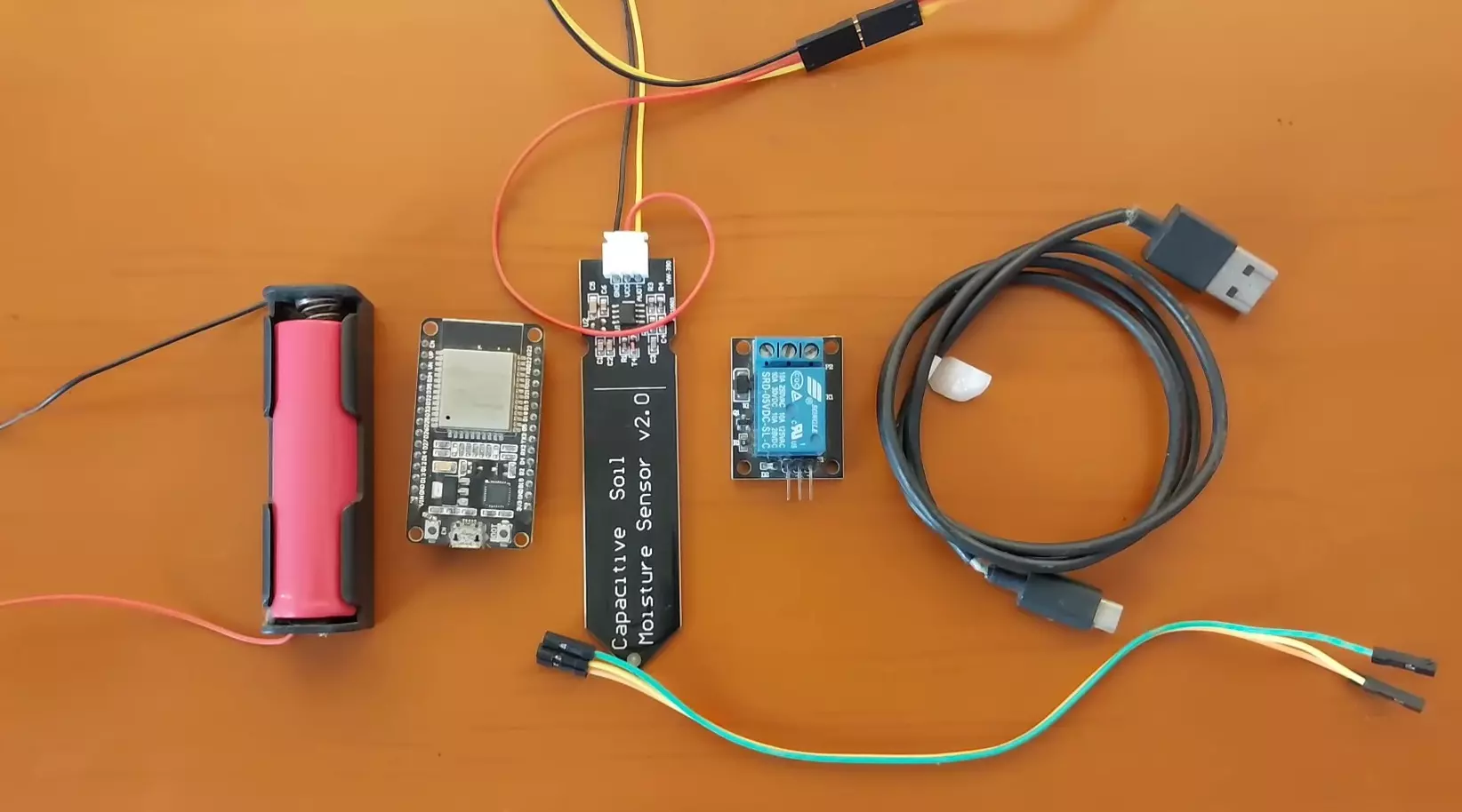
🔩 Required Components
| Component | Quantity |
|---|---|
| ESP32 Dev Board | 1 |
| Soil Moisture Sensor | 1 |
| 1-Channel Relay Module | 1 |
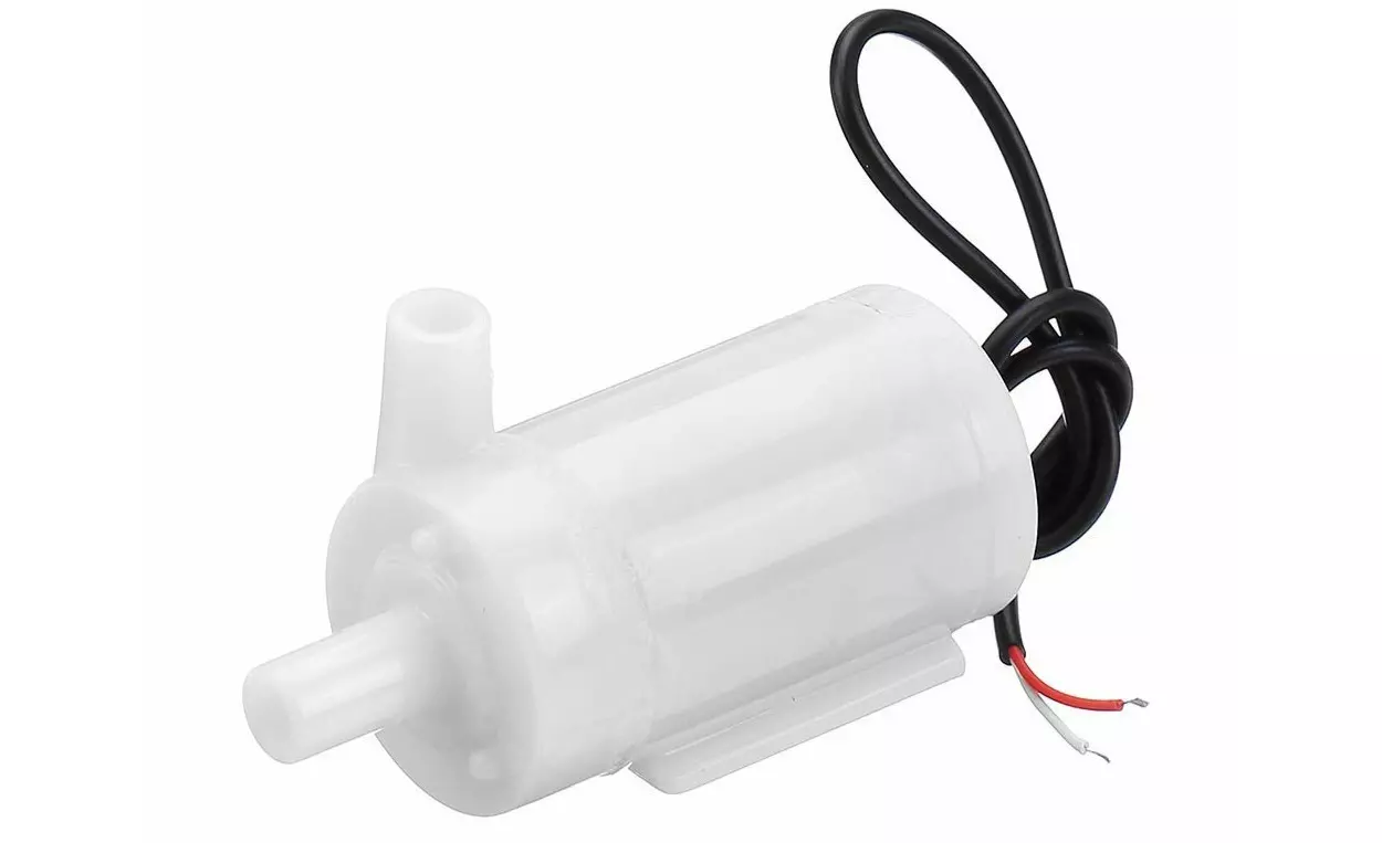
| Submersible Water Pump | 1 |
| Power Supply (5V) | 1 |
| Connecting Wires | – |
| Smartphone with Blynk | 1 |
📘 Automatic Irrigation System Circuit Diagram
Here’s a simplified circuit representation:
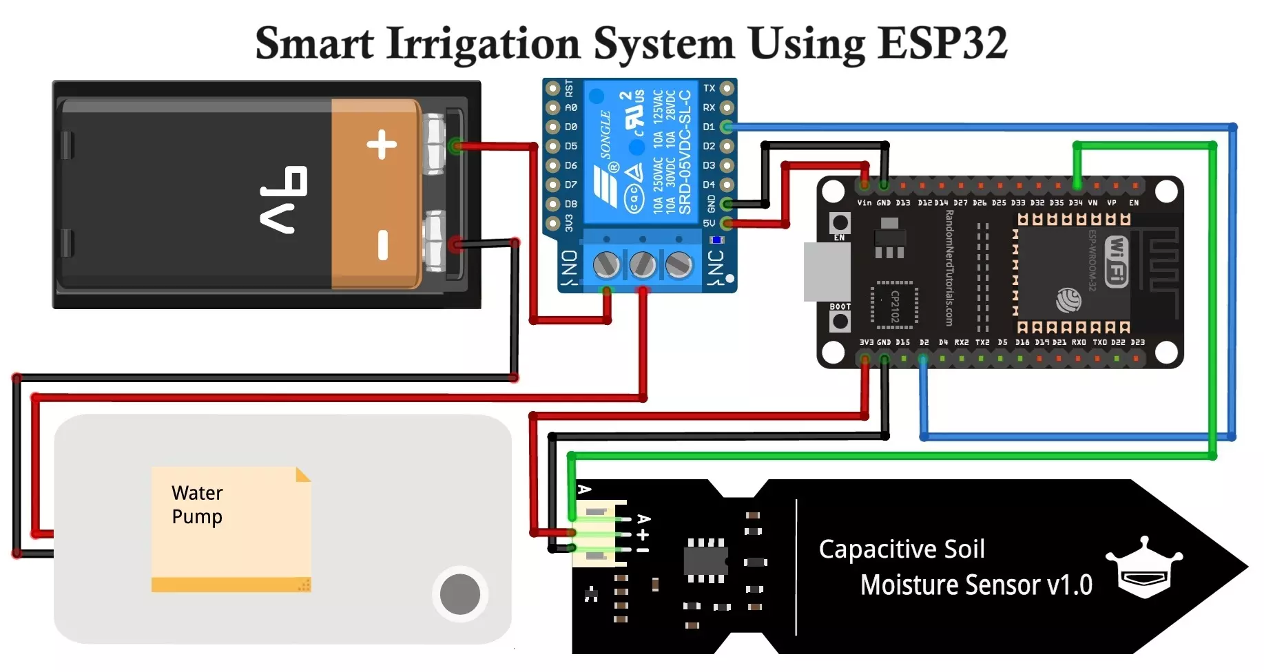
🧩 Component Pin Connections
| Component | ESP32 Pin |
|---|---|
| Soil Moisture Sensor | GPIO34 (Analog In) |
| Relay Module (Pump) | GPIO2 (Digital Out) |
| VCC (Sensors/Relay) | 3.3V/5V (As needed) |
| GND | GND |
Note: Use a transistor or opto-isolator with the relay if switching high currents.
🛠️ Assembly Instructions
- Connect Soil Moisture Sensor
- VCC to 3.3V (or 5V if required)
- GND to GND
- Signal to GPIO34
- Relay and Pump Setup
- Relay IN to GPIO2
- VCC and GND to ESP32 5V and GND
- Pump connected to NO (Normally Open) of relay and 5V DC power supply.
- Place a diode across the pump terminals for back EMF protection.
- Blynk Configuration
- Create a Blynk template and device
- Add virtual widgets:
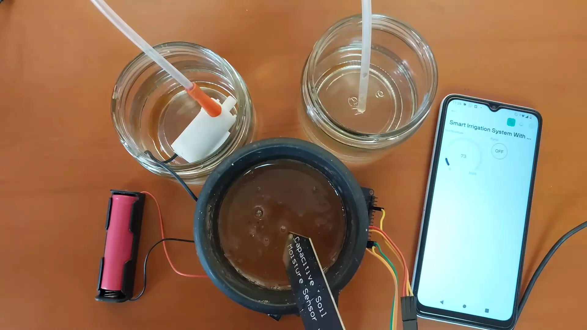
- Gauge (V5) → Soil Moisture %
- Switch (V6) → Manual Pump ON/OFF
- Copy the
BLYNK_TEMPLATE_ID,BLYNK_TEMPLATE_NAME, andBLYNK_AUTH_TOKENto your code.
⚙️ Working of Smart Irrigation System
- Startup
- ESP32 connects to Wi-Fi and syncs with Blynk.
- Sensor Reading
- Every 3 seconds, it reads the soil moisture sensor.
- Decision Logic
- If moisture is below threshold → activate pump
- If above threshold and not manually forced → deactivate pump
- Remote Control & Feedback
- User can manually override via app switch.
- Moisture readings are updated in the app dashboard.
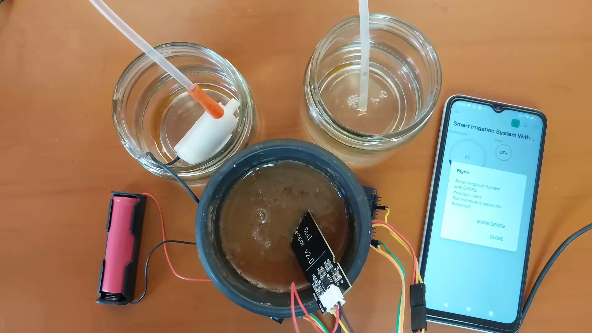
- Alerts notify when automatic watering is triggered.
💻 Code Explanation
- ESP32 reads the soil moisture level from the analog pin.
- Converts the analog value to percentage (0-100%).
- If the moisture is below a threshold (e.g., 60%), the pump is turned on automatically.
- You can also manually turn the pump on/off via the Blynk app switch (V6).
- Real-time data is sent to Blynk for monitoring.
- Notification alert sent if pump activates due to dry soil.
#define BLYNK_TEMPLATE_ID "TMPL3yY1GKAGn"
#define BLYNK_TEMPLATE_NAME "Smart Irrigation System with ESP32"
#define BLYNK_AUTH_TOKEN "wNUHEqkHCdbaOMYdShu2xRt3wUsopzcc"

#define BLYNK_PRINT Serial
#include <WiFi.h>
#include <BlynkSimpleEsp32.h>

#define SOIL_MOISTURE_PIN 34 // Analog pin for soil moisture sensor
#define THRESHOLD_MOISTURE 60 // Adjust this value based on your sensor readings (0-100)
#define PUMP_PIN 2 // Digital pin for controlling the pump
#define PUMP_SWITCH V6 // Virtual pin for controlling the pump manually

char auth[] = BLYNK_AUTH_TOKEN; // Replace with your Blynk auth token
char ssid[] = "WiFi Username"; // Replace with your WiFi credentials
char pass[] = "WiFi Password";

BlynkTimer timer;

bool isPumpOn = false; // Variable to track pump status

// Function to smooth the sensor readings (average over 10 readings)
int readSoilMoisture() {
int totalMoisture = 0;
for (int i = 0; i < 10; i++) {
totalMoisture += analogRead(SOIL_MOISTURE_PIN);
delay(10); // Small delay to stabilize readings
}
return totalMoisture / 10; // Average reading
}

void sendSensorData() {
int soilMoisture = readSoilMoisture();
Serial.print("Raw Soil Moisture: ");
Serial.println(soilMoisture);

// Map the analog sensor values to a percentage (0-100)
int soilMoisturePercentage = map(soilMoisture, 4095, 0, 0, 100); // Adjust this mapping based on your sensor's characteristics
Serial.print("Soil Moisture Percentage: ");
Serial.println(soilMoisturePercentage);

// Send soil moisture data to Blynk
Blynk.virtualWrite(V5, soilMoisturePercentage);

// Check if the pump should be on based on manual switch or soil moisture level
if (isPumpOn || soilMoisturePercentage < THRESHOLD_MOISTURE) {
// Turn on the pump
digitalWrite(PUMP_PIN, HIGH);
// Check if the pump is turned on automatically (not manually)
if (!isPumpOn) {
// Send alert notification to Blynk app if the pump is turned on automatically
Blynk.logEvent("moisture_alert", "Soil moisture is below the threshold!");
Serial.println("Soil moisture is below the threshold!");
}
} else {
// Turn off the pump only if it was not turned on manually
if (!isPumpOn) {
digitalWrite(PUMP_PIN, LOW);
}
}
}

BLYNK_WRITE(PUMP_SWITCH)
{
isPumpOn = param.asInt();
if (isPumpOn) {
Serial.println("Pump manually turned ON");
} else {
Serial.println("Pump manually turned OFF");
}
}

void setup()
{
Serial.begin(9600);
pinMode(PUMP_PIN, OUTPUT); // Set pump pin as an output

Blynk.begin(auth, ssid, pass);

timer.setInterval(3000L, sendSensorData); // Set the interval for checking soil moisture (every 3 seconds)

// Setup switch widget
Blynk.virtualWrite(PUMP_SWITCH, isPumpOn);
Blynk.syncVirtual(PUMP_SWITCH);
}

void loop()
{
Blynk.run();
timer.run();
}
This code is for a Smart Irrigation System using an ESP32 and Blynk. It monitors soil moisture and controls a water pump automatically or manually through the Blynk mobile app.
Here’s a breakdown of the code:
📌 1. Definitions and Library Inclusions
#define BLYNK_TEMPLATE_ID "TMPL3yY1GKAGn"
#define BLYNK_TEMPLATE_NAME "Smart Irrigation System with ESP32"
#define BLYNK_AUTH_TOKEN "wNUHEqkHCdbaOMYdShu2xRt3wUsopzcc"
#define BLYNK_PRINT Serial
- These define the Blynk Template ID, project name, and auth token needed to connect your device to the Blynk platform.
BLYNK_PRINT Serialallows Blynk debug prints to show on the serial monitor.
#include <WiFi.h>
#include <BlynkSimpleEsp32.h>
- Includes the required libraries for WiFi and Blynk on an ESP32.
📌 2. Pin Definitions and Constants
#define SOIL_MOISTURE_PIN 34
#define THRESHOLD_MOISTURE 60
#define PUMP_PIN 2
#define PUMP_SWITCH V6
SOIL_MOISTURE_PIN: Analog input pin connected to the soil moisture sensor.THRESHOLD_MOISTURE: If moisture falls below this percentage, the pump turns on.PUMP_PIN: Digital output to control a relay or pump.PUMP_SWITCH: Virtual pin in Blynk app for manual pump control.
📌 3. WiFi and Blynk Credentials
char auth[] = BLYNK_AUTH_TOKEN;
char ssid[] = "WiFi Username";
char pass[] = "WiFi Password";
- Replace these with your own WiFi network and Blynk token to make the device connect to the internet and the app.
📌 4. Global Variables
BlynkTimer timer;
bool isPumpOn = false;
timer: Blynk’s internal timer used to run functions periodically.isPumpOn: Tracks manual pump state.
📌 5. Reading Soil Moisture
int readSoilMoisture() {
  int totalMoisture = 0;
  for (int i = 0; i < 10; i++) {
    totalMoisture += analogRead(SOIL_MOISTURE_PIN);
    delay(10);
  }
  return totalMoisture / 10;
}
- Reads soil moisture 10 times and averages the values to reduce sensor noise.
📌 6. Sending Data to Blynk & Controlling Pump
void sendSensorData() {
  int soilMoisture = readSoilMoisture();
  int soilMoisturePercentage = map(soilMoisture, 4095, 0, 0, 100);
  Blynk.virtualWrite(V5, soilMoisturePercentage);
- Sends soil moisture percentage to virtual pin V5.
- The
map()function converts analog value (0–4095) to a 0–100 percentage.
  if (isPumpOn || soilMoisturePercentage < THRESHOLD_MOISTURE) {
    digitalWrite(PUMP_PIN, HIGH);
    if (!isPumpOn) {
      Blynk.logEvent("moisture_alert", "Soil moisture is below the threshold!");
    }
  } else {
    if (!isPumpOn) {
      digitalWrite(PUMP_PIN, LOW);
    }
  }
}
- Pump is turned ON if:
- Manually triggered (
isPumpOn == true), or - Soil is too dry (moisture below threshold).
- Manually triggered (
- A Blynk alert is sent if the system automatically turns on the pump.
📌 7. Manual Pump Control
BLYNK_WRITE(PUMP_SWITCH)
{
  isPumpOn = param.asInt();
  if (isPumpOn) {
    Serial.println("Pump manually turned ON");
  } else {
    Serial.println("Pump manually turned OFF");
  }
}
- Reads the virtual switch V6 state from Blynk app to manually turn the pump ON/OFF.
📌 8. Setup
void setup()
{
  Serial.begin(9600);
  pinMode(PUMP_PIN, OUTPUT);
  Blynk.begin(auth, ssid, pass);
  timer.setInterval(3000L, sendSensorData);
  Blynk.virtualWrite(PUMP_SWITCH, isPumpOn);
  Blynk.syncVirtual(PUMP_SWITCH);
}
- Initializes serial, pump pin, connects to Blynk.
- Sets the sensor reading function to run every 3 seconds.
- Syncs the app’s virtual switch state to match the current pump state.
📌 9. Loop
void loop()
{
  Blynk.run();
  timer.run();
}
- Keeps the Blynk connection and periodic functions running.
✅ Advantages
- 🌱 Water Conservation: Uses water only when needed.
- 📱 Remote Access: Full control from anywhere via smartphone.
- 🤖 Automation: Reduces human effort and error.
- 🌐 Real-Time Monitoring: Stay updated with current soil conditions.
- 📢 Smart Alerts: Notifications on low moisture prevent crop damage.
- 💸 Low Cost: Affordable hardware and free Blynk platform (basic use).
❌ Disadvantages
- 📶 Wi-Fi Dependent: Needs constant internet connection.
- 🔋 Power Requirement: ESP32 and pump need stable power.
- 🌦️ Sensor Degradation: Moisture sensors may corrode over time.
- 💧 Calibration Needed: Sensor readings need to be mapped accurately to real soil conditions.
- 📱 App Learning Curve: Blynk app requires initial setup and configuration.
🚜 Applications
- 🌾 Smart Farming: Automate irrigation in fields and greenhouses.
- 🌼 Gardening: Ideal for home gardens and flower beds.
- 🪴 Potted Plants: Monitor and water indoor/outdoor potted plants.
- 🏫 Educational Projects: Excellent DIY for learning IoT and automation.
- 🏢 Urban Landscaping: Used in parks or commercial spaces with greenery.
🧠 Future Improvements
- Add DHT11/DHT22 sensor for temperature & humidity sensing.
- Use rain sensors to prevent irrigation during rainfall.
- Add OLED/Nextion display for local display of readings.
- Implement cloud logging or email reports.
- Use solar panel + battery backup for outdoor deployment.
🧾 Conclusion
This Smart IoT-Based Irrigation System using ESP32 is a powerful DIY project that merges IoT, automation, and agricultural innovation. It offers a sustainable, smart, and convenient way to ensure that plants receive the right amount of water at the right time. This project:
- Monitors soil moisture.
- Automatically turns on the water pump when soil is dry.
- Allows manual control via Blynk app.
- Sends sensor data to Blynk dashboard.
- Notifies user if moisture is low.
By combining ESP32, Blynk, and basic sensors, you can create a reliable system to support your garden or farm – all while monitoring everything from the palm of your hand.
DIY 433MHz RF Remote Control Car Circuit Diagram and Working
BME680 and ESP8266 Based Indoor Air Quality Monitoring System
