Let’s designing a PIR motion sensor circuit that uses a Passive Infrared (PIR) sensor to control a buzzer through a 555 timer for motion detection applications. Here’s a step-by-step guide to creating this circuit:
Working Principle of PIR Motion Sensor:
A Passive Infrared (PIR) motion sensor detects motion by sensing changes in infrared radiation. Here’s how it works:
- Infrared Radiation
All objects emit infrared radiation depending on their temperature and surface properties. For instance, the human body emits most of its energy in the 8 μm to 12 μm wavelength range. - PIR Sensor Design
The sensor consists of two pyroelectric sensors placed side by side. These sensors detect heat energy from the surrounding environment. - Detection of Change
When an object moves through the sensor’s field of view, it causes a variation in the temperature. This results in a detectable change in infrared radiation. - Signal Output
The sensor translates these changes in infrared radiation into a varying output voltage. This signal then triggers an action, such as activating an alarm, sending a notification, or switching on a light.
Components Needed:
- PIR sensor
- 555 timer IC
- Buzzer
- Resistors (various shown below)
- Capacitors (various shown below)
- NPN transistor (e.g., 2N2222 or BC547)
- Diode (e.g., 1N4148 or 1N4001)
- Power supply (5V or 9V, depending on your components)
- Breadboard and connecting wires
| Name | Quantity | Component |
| PIR1 | 1 | PIR Sensor |
| U1 | 1 | Timer |
| T1, T2 | 2 | NPN Transistor (BJT) |
| D1 | 1 | Red LED |
| C1 | 1 | 10 uF, 25 V Polarized Capacitor |
| R3 | 1 | 10 kΩ Resistor |
| R2 | 1 | 1 kΩ Resistor |
| P1 | 1 | 5V Power Supply |
| PIEZO | 1 | Piezo |
| C2 | 1 | 10 nF Capacitor |
| R1 | 1 | 220 Ω Resistor |
PIR Motion Sensor Circuit Diagram:
Below is the circuit diagram showing components and their connections.
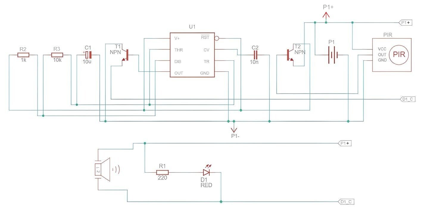
PIR Sensor Connections:
- P1+: Connect to +Vcc (5V or 9V)
- GND: Connect to Ground (GND)
- OUT: This is the output pin, which goes high (usually to +Vcc) when motion is detected.
- Connect OUT pin to base of transistor (T2) which connects pin 4 and 8 to +Vcc.
555 Timer Configuration:
- GND (Pin 1): Connect to Ground
- TRIG (Pin 2): Connect to pin 6 and capacitor (C1)
- OUT (Pin 3): This will go to the base of the transistor (T1)
- RESET (Pin 4): Connect to +Vcc via transistor (T2)
- CONTROL (Pin 5): Connect to Ground via a small capacitor (C2) (optional, typically 10nF)
- THRE (Pin 6): Connect to Pin 2 (TRIG)
- DISCH (Pin 7): Connect to the junction of (R2) and (R3)
- VCC (Pin 8): Connect to +Vcc via transistor (T2)
Transistor and Buzzer:
- Connect the collector of the NPN transistor (T1) to Ground.
- Connect one terminal of the buzzer (D1_C) to Ground via transistor (T1).
- Connect the other terminal (P1+) of the buzzer to Vcc.
- LED’s anode to Vcc, cathode to (D1_C) via (R1).

Astable Mode Configuration of 555 Timer:
To determine the frequency of a 555 timer configured in astable mode, we need to calculate the time intervals for the high and low states of the output signal. In astable mode, the 555 timer continuously oscillates between high and low states, creating a square wave output.
In astable mode, the 555 timer uses two resistors (R1 and R2) and a capacitor (C). Determining the frequency of oscillation,
If we keep the value of the capacitor C to 10 µF while keeping the resistor values R2 = 1 kΩ and R3 = 10 kΩ, we need to calculate the high time (t_high), low time (t_low), total period (T), and frequency (f).
Given Values:
– R2 = 1 kΩ
– R3 = 10 kΩ
– C = 10 µF
Calculating the Timing Intervals and Frequency:
High Time (t_high):
t_high = 0.693 * (R2 + R3) * C
t_high = 0.693 * (1,000 Ω + 10,000 Ω) * 10 * 10^-6 F
t_high = 0.693 * 11,000 Ω * 10 * 10^-6
t_high = 0.693 * 0.11
t_high ≈ 0.07623 s
Low Time (t_low):
t_low = 0.693 * R3 * C
t_low = 0.693 * 10,000 Ω * 10 * 10^-6 F
t_low = 0.693 * 0.1
t_low ≈ 0.0693 s
Total Period (T):
T = t_high + t_low
T = 0.07623 s + 0.0693 s
T ≈ 0.14553 s
Frequency (f):
f = 1 / T
f ≈ 1 / 0.14553 s
f ≈ 6.87 Hz
With R2 = 1 kΩ, R3 = 10 kΩ, and C = 10 µF, the frequency of the 555 timer in astable mode is approximately 6.87 Hz.
Testing the Circuit:
- Power the circuit.
- Move in front of the PIR sensor.
- The PIR sensor should detect motion, sending a high signal to the 555 timer.
- The 555 timer will output a square pulse signal, turning on the transistor (T2).
- The transistor (T2) will activate the buzzer.
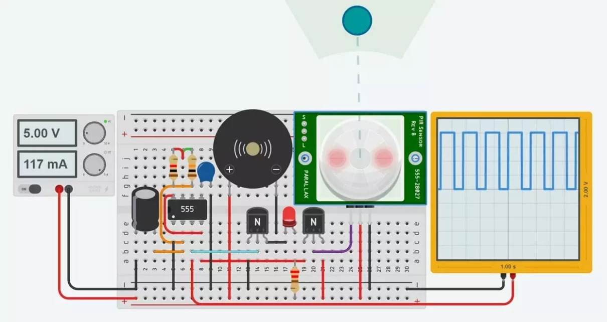
PIR Sensor Tinkercad Simulation:
Here is the tinkercad simulation of the above circuit.
This simple circuit uses the 555 timer in astable mode to turn on buzzer, when motion is detected by the PIR sensor.

What is the working principle for this can u explain in detail plz
I have added explanation please have a look
THANK U YOU ARE SO GOOD TO ME