The term “Piezo” in Piezoelectric Transducer originates from the Greek word piezein, meaning “to press” or “to squeeze.” This etymology reflects the fundamental principle of piezoelectricity—a phenomenon in which mechanical pressure generates an electrical voltage.
Piezoelectric transducers (sensor / Actuator) harness this effect to convert mechanical energy (such as pressure, force, vibration, or acceleration) into electrical signals, and vice versa. These electromechanical devices are essential in a wide range of applications, from medical imaging and industrial monitoring to consumer electronics and automotive safety systems. Their ability to provide precise measurement and control makes them invaluable components in modern electronic systems.
Symbol of Piezoelectric Transducer
The standard symbol for a piezoelectric transducer resembles that of a capacitor, sometimes annotated with “PZT” (Lead Zirconate Titanate) or labeled explicitly.

Sometimes, it is represented as a crystal resonator (especially in oscillators), which looks like a rectangle with two vertical lines.
Construction of Piezoelectric Transducer
The core of a piezoelectric sensor is a piezoelectric material that generates electric charge when mechanically stressed. A typical piezoelectric transducer is made up of:
- Piezoelectric Crystal: Material like Quartz, PZT, or Barium Titanate.
- Metal Electrodes: Placed on both sides of the crystal to collect charge.
- Backing Material or Housing: Provides mechanical stability and can tune the frequency response.
- Protective Casing: Shields the device from moisture, dust, and mechanical damage.
Working of Piezoelectric Transducer
A piezoelectric transducer is a device that converts mechanical energy into electrical energy, or vice versa, using the piezoelectric effect. It consists of a piezoelectric material (such as quartz or lead zirconate titanate) placed between two electrodes.
When mechanical stress (like pressure or vibration) is applied, the material produces a voltage. Conversely, when a voltage is applied, the material deforms physically. These two effects form the basis for both sensing and actuation.
Piezoelectric Effect
- The piezoelectric effect refers to the generation of electric charge when certain materials are mechanically deformed.
- When pressure, force, or vibration is applied to the crystal:
- The atomic structure becomes asymmetrical.
- Positive and negative charges shift within the crystal.
- A voltage appears across its surfaces.
- The voltage is proportional to the amount of mechanical stress.
This is used in sensors, where mechanical input is converted into an electrical signal.
Inverse Piezoelectric Effect
- The inverse piezoelectric effect occurs when an electric field is applied to a piezoelectric material, causing it to mechanically deform (expand or contract).
- This deformation is very precise and occurs at high frequency if the voltage is alternating.
This is used in actuators, where electrical input is converted into mechanical movement.
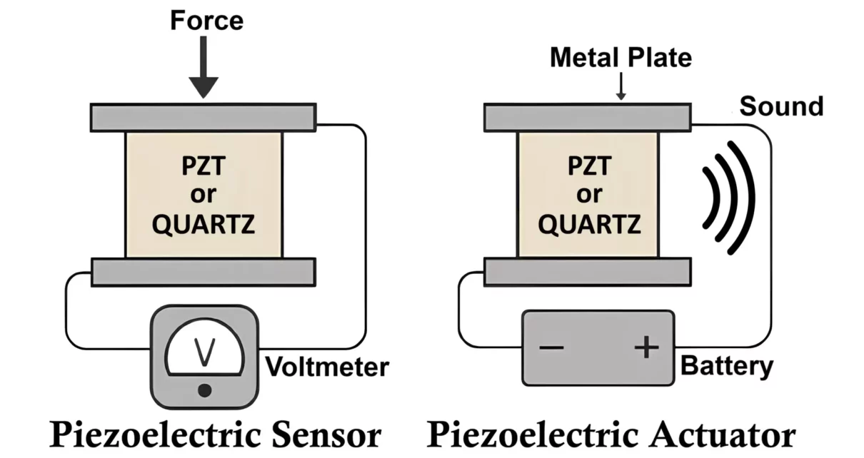
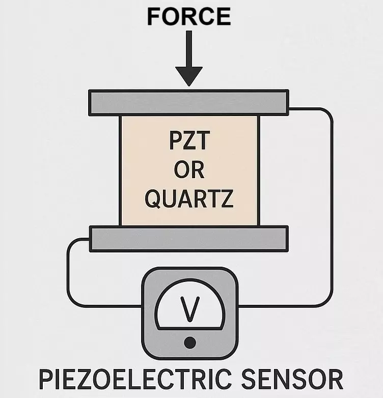
Piezoelectric Sensor
A piezoelectric sensor uses the direct piezoelectric effect to measure physical quantities such as: Pressure, Force, Vibration, Acceleration.
⚠️ Note: Piezo sensors respond only to dynamic (changing) forces. Constant pressure does not produce a sustained output.
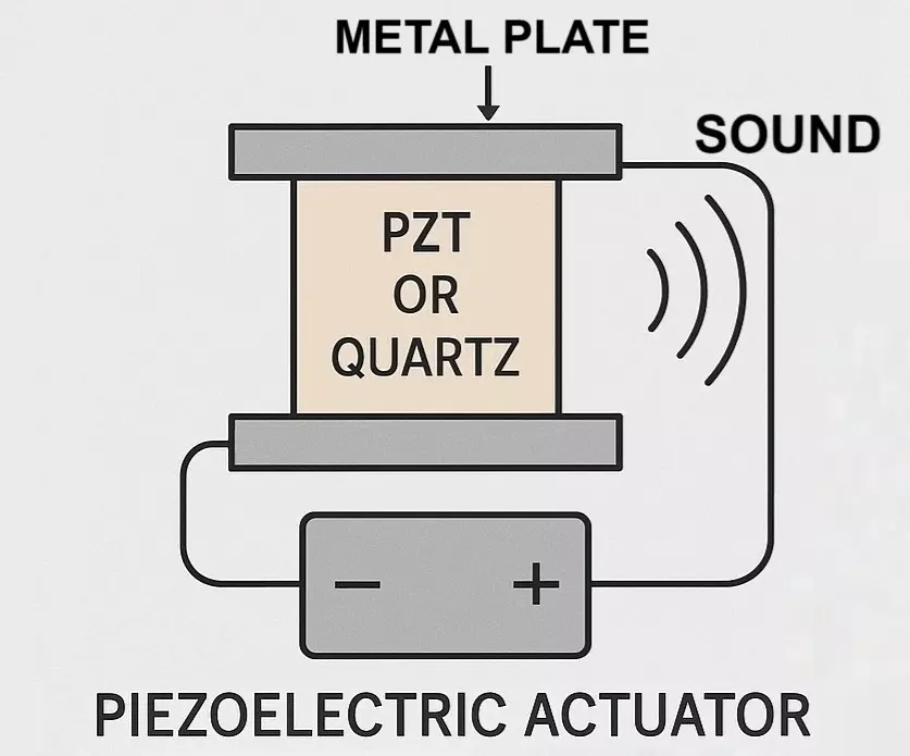
Piezoelectric Actuator
A piezoelectric actuator uses the inverse piezoelectric effect to produce precise mechanical movement in response to an electrical signal. These are used in:
- Precision positioning (e.g., microscopes, optics)
- Inkjet printers
- Ultrasound generation (medical imaging, industrial inspection)
Types of Piezoelectric Materials
1. Naturally Occurring Piezoelectric Materials:
These materials exhibit piezoelectric properties in their natural form without human modification.
- Minerals: Quartz, Rochelle salt (sodium potassium tartrate), Topaz, Tourmaline-group minerals.
- Organic Substances: Silk, wood, enamel, bone, hair, natural rubber, dentin.
2. Artificially Manufactured Piezoelectric Materials:
These are engineered materials designed to exhibit or enhance piezoelectric effects, commonly used in electronics and sensors.
- Polymers: Polyvinylidene fluoride (PVDF or PVF₂).
- Ceramics and Crystals: Barium titanate (BaTiO₃), Lead titanate (PbTiO₃), Lead zirconate titanate (PZT), Potassium niobate (KNbO₃), Lithium niobate (LiNbO₃), Lithium tantalate (LiTaO₃), other lead-free piezoelectric ceramics.
Each material has trade-offs:
- Quartz: Very stable but low output.
- Rochelle Salt: High output but sensitive to temperature and humidity.
Ideal materials for transducer design should offer:
- Frequency stability
- High output sensitivity
- Environmental robustness
- Shape adaptability
Types of Piezoelectric Transducers
Based on Material:
- Natural: Quartz, Tourmaline, Rochelle Salt
- Synthetic: PZT, Barium Titanate, PVDF (Polyvinylidene Fluoride)
By Function:
- Sensors: Convert force/pressure/vibration into electric signals.
- Actuators: Use electricity to generate movement.
- Ignitors: Generate high-voltage sparks (e.g., lighters).
- Accelerometers: Measure vibrations and motion.
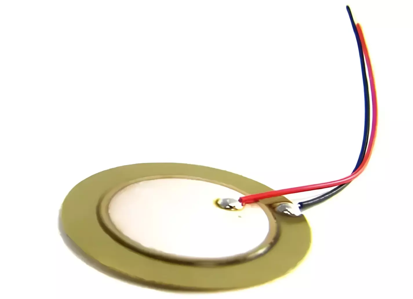
Based on Shape:
- Disc, Beam, Plate, Ring, Tube configurations.
By Application:
- Piezoelectric Accelerometer: Measures acceleration/vibration.
- Piezoelectric Microphone: Converts sound pressure into voltage.
- Piezo Buzzer/Actuator: Converts voltage to sound.
- Ultrasonic Transceiver: Generate and receive ultrasonic waves.
Piezoelectric Sensor Circuit
The equivalent circuit of a piezoelectric sensor models its electrical behavior, which results from its electromechanical properties. This model helps in understanding how the sensor responds to mechanical stress and how it interfaces with electronics.
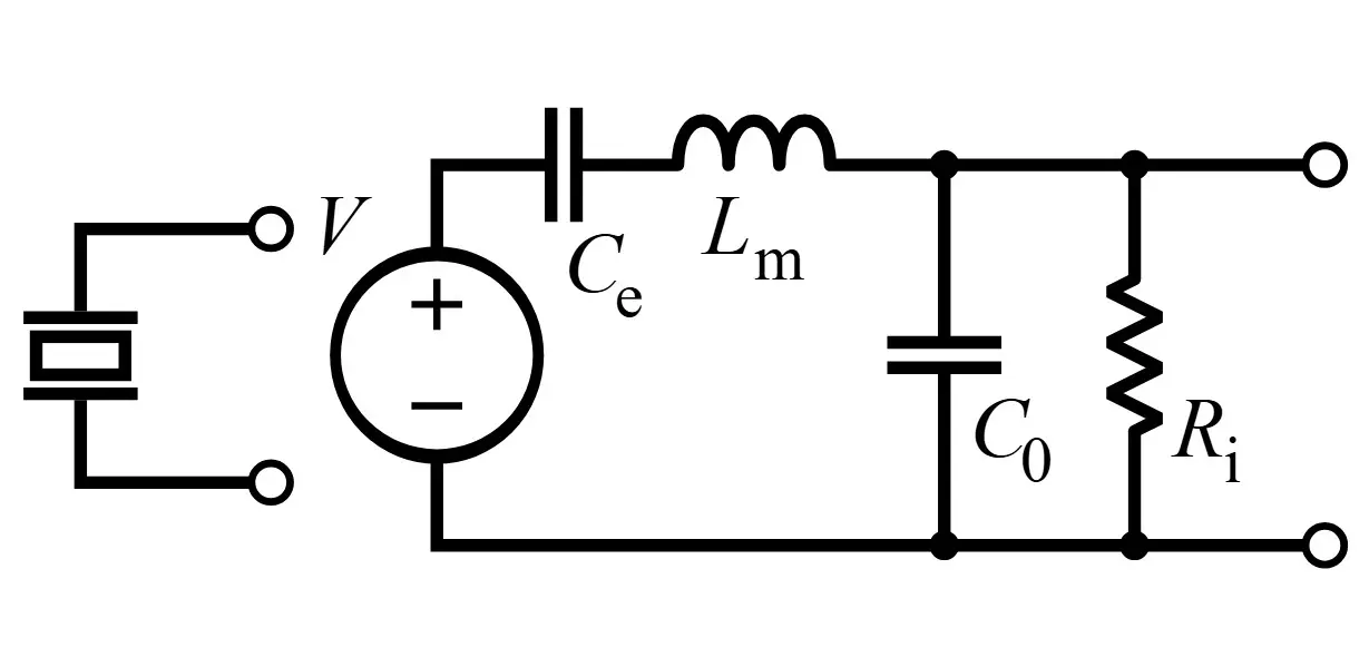
A simplified equivalent circuit of a piezoelectric sensor includes:
| Element | Represents |
|---|---|
| V | Generated piezoelectric voltage |
| Ce | Compliance or stiffness of the sensor (motional capacitance) |
| Lm | Mass or inertia of the vibrating structure |
| C0 | Static capacitance due to electrodes/material |
| Ri | Leakage resistance (dielectric loss) |
Proper signal conditioning (buffer, amplifier, filter) is essential to convert the high-impedance output into usable signals.
a. Voltage Source V
This is the piezoelectric voltage generated due to mechanical deformation (stress or vibration). It’s a function of the mechanical input, and it’s modeled as an ideal voltage source.
b. Series Elements: Ce and Lm
- Ce (Effective series capacitance): Represents the compliance of the piezoelectric material under mechanical stress.
- Lm (Motional inductance): Represents the mass or inertia of the mechanical system (i.e., it reflects the mechanical resonance due to the inertia of the vibrating structure).
Together, Lm and Ce form a series resonant branch, modeling the electromechanical resonance behavior of the piezoelectric sensor.
c. Parallel Branch: C0 and Ri
- C0 (Static Capacitance): This is the electrical capacitance of the sensor when it is not under mechanical motion. It’s due to the dielectric nature of the piezoelectric material and the geometry of the electrodes.
- Ri (Insulation Resistance): Represents the leakage path within the piezoelectric material. It accounts for losses due to imperfect insulation.
This model is crucial in designing amplifiers, filters, or impedance-matching networks for piezoelectric sensors in Vibration measurement, Ultrasonic transducers and Pressure sensing.
Resonant Behavior
- The series LC branch (Ce and Lm) resonates at a particular mechanical resonance frequency, denoted by:
Fr = 1/(2π√LmCe)
- At this frequency, the sensor is most sensitive, and the voltage output peaks.
- The parallel branch (C0 and Ri) dominates the sensor behavior outside the resonance, especially at higher frequencies, where C0 starts to shunt the signal.
Piezoelectric Transducer Formula
The electrical charge Q produced by a piezoelectric material is given by:
- Longitudinal Mode:
Q = F⋅d - Transverse Mode:
Q = F⋅d⋅(b/a)
where:- F = applied force
- d = piezoelectric charge coefficient (for quartz, ≈ 2.3 × 10⁻¹² C/N)
- b/a = geometric factor, where increasing this ratio increases the output in transverse mode.
- b = length of the piezoelectric element in the direction of the force.
- a = thickness of the piezoelectric element in the direction of polarization.
Advantages of Piezoelectric Transducers
- High Sensitivity: Detects minute vibrations and pressure changes.
- Fast Response Time: Ideal for dynamic measurements (vibration, shock).
- Compact Size: Easy integration into small systems.
- No External Power for Sensing: Generates its own signal upon mechanical input.
- Wide Frequency Range: Especially in ultrasonic applications.
- Durable & Long-lasting: Especially in sealed or rugged environments.
Disadvantages of Piezoelectric Transducers
- Not Suitable for Static Measurements: They can’t measure steady forces as charge leakage occurs.
- High Impedance Output: Needs impedance matching or buffering.
- Sensitive to Temperature: Performance can degrade under extreme heat.
- Aging and Depolarization: Especially in synthetic ceramics like PZT.
- Mechanical Fragility: Crystals can crack under excessive stress.
Applications of Piezoelectric Transducers
Medical:
- Ultrasound Imaging (Sonography): Piezoelectric crystals vibrate to generate ultrasound waves; reflected echoes form real-time diagnostic images.
- Electronic Stethoscopes: Use piezoelectric elements to detect and amplify internal body sounds with high sensitivity.
- Lithotripsy: Focused ultrasonic pulses generated by piezo elements break down kidney stones non-invasively.
- Piezo-based Surgical Tools: Enable precise cutting and tissue manipulation using ultrasonic vibrations for minimally invasive procedures.
Household Devices:
- Gas Lighters: Trigger creates spark via piezoelectric crystal.
- Humidifiers & Inkjet Printers: Use piezo actuators for fluid control.
Construction & Civil:
- Stress Monitoring in Columns: Measures voltage generated under load.
Industrial:
- Engine Knock Sensors
- Machinery Vibration Monitoring
- Ultrasonic Welding and Cleaning
- Fuel Injector Actuation
- Pressure and force sensors in automation
Automotive:
- Airbag Deployment Sensors
- Pressure & Acceleration Sensors
- Engine knock sensors
- Tire pressure monitoring
Consumer Electronics:
- Piezo buzzers in alarms, timers, and watches
- Touch buttons in appliances
- Microphones and speakers
- Crystal Oscillators
Music & Audio:
- Piezoelectric Microphones
- Instrument Pickups (like for guitars)
Aerospace & Defense:
- Missile guidance sensors
- Structural health monitoring in aircraft
- Vibration and shock sensors
Environment & Research:
- Seismic and earthquake detection
- Wind and pressure sensing
- Energy harvesting from vibrations
Piezoelectric Transducer Summary
| Feature | Description |
|---|---|
| Working Principle | Piezoelectric effect – mechanical ↔ electrical |
| Core Material | Quartz, PZT, Barium Titanate, PVDF |
| Response Type | Dynamic (vibrations, impacts) |
| Output | Voltage proportional to force/pressure |
| Applications | Sensors, buzzers, medical imaging, etc. |
| Advantages | Sensitive, fast, compact, reliable |
| Disadvantages | No DC/static force sensing, high impedance |
Conclusion
The piezoelectric transducer is a versatile device that converts mechanical stress into electrical signals and vice versa, without requiring an external power source. Its fast response, high sensitivity, and compact size make it indispensable in many applications — from consumer electronics to aerospace and healthcare.
Key points:
- Operates based on stress-induced charge separation in piezoelectric materials.
- Ideal for measuring dynamic forces, though less effective for static loads.
- Widely used in sensors and actuators for precise and reliable performance.
Understanding piezoelectric transducers enables the development of innovative, responsive technologies across diverse industries, driving progress in sensing, imaging, and control systems.
What is a Sensor? Types of Sensors, Classification & Applications
BME680 and ESP8266 Based Indoor Air Quality Monitoring System
Light Dependent Resistor (LDR) / Photoresistor Circuit Diagram & Working
