Capacitors are fundamental passive components used in electronic circuits for energy storage, filtering, coupling, and timing. Among them, Non-polar or Non-polarized Capacitors hold a special place because they can operate with AC signals and DC voltages of either polarity. Their versatility and stability make them essential in audio systems, RF circuits, SMPS, industrial power systems, and many precision applications.
This article provides an in-depth, modern, and comprehensive description of non-polarized capacitors, their symbol, detailed types, construction methods, working principle, and practical applications.
What is a Non-Polar Capacitor?
A non-polar capacitor is a capacitor that does not have a fixed polarity, meaning its terminals are interchangeable. Unlike electrolytic capacitors, which must be connected with correct polarity, non-polarized capacitors:
- Can work with both AC and DC
- Are safe with reversed polarity
- Offer lower capacitance values but higher voltage ratings
- Are more stable over temperature and frequency
Key Characteristics
- Typical capacitance: pF to a few µF
- Voltage rating: a few volts to several thousand volts
- Highly stable, low losses, and long lifespan
- Cheaper than electrolytic capacitors in lower values
Symbol
Non-polar capacitor symbol uses two parallel straight plates:
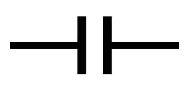
No positive (+) or negative (−) sign is shown.
Construction and Working Principle
Non-polarized capacitors are built using:
- Two conductive metal plates (copper, aluminum, nickel)
- A dielectric (ceramic, mica, polymer film)
- Protective encapsulation (epoxy, plastic, resin)
Related Articles:
- Types of Capacitors with Symbol, Classification and Applications
- Difference Between Coupling, Decoupling, and Bypass Capacitors
- Ceramic vs Electrolytic Capacitor: Key Differences and Applications
- Polarized Capacitors – Symbol, Types, Construction, Working, Uses
Construction Process
- A thin dielectric layer is placed between metal plates.
- For multilayer capacitors, alternating layers are stacked.
- Leads or terminals are attached.
- Assembly is coated, dipped, or sealed to protect from moisture and mechanical damage.

Working Principle
Non-polarized capacitors operate by storing energy in an electric field between two plates. When AC is applied:
- Voltage polarity reverses continuously.
- Charge distribution flips accordingly.
- Dielectric polarizes and depolarizes without degradation.
The absence of an electrolyte makes them immune to polarity, offering exceptional reliability.
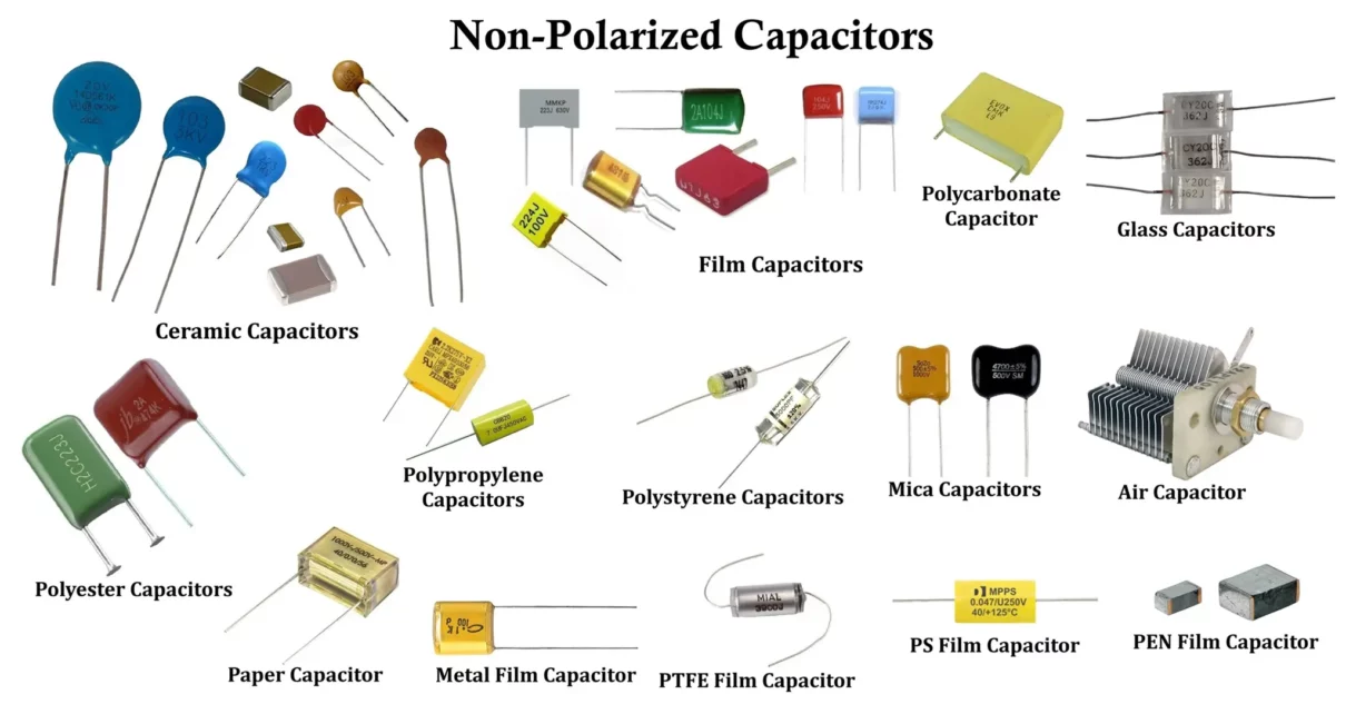
Types of Non-Polar Capacitors
Non-polarized capacitors are classified into three major categories:
- Ceramic Capacitors
- Mica Capacitors
- Film Capacitors
Each category includes several subtypes, each optimized for specific electrical and environmental conditions.
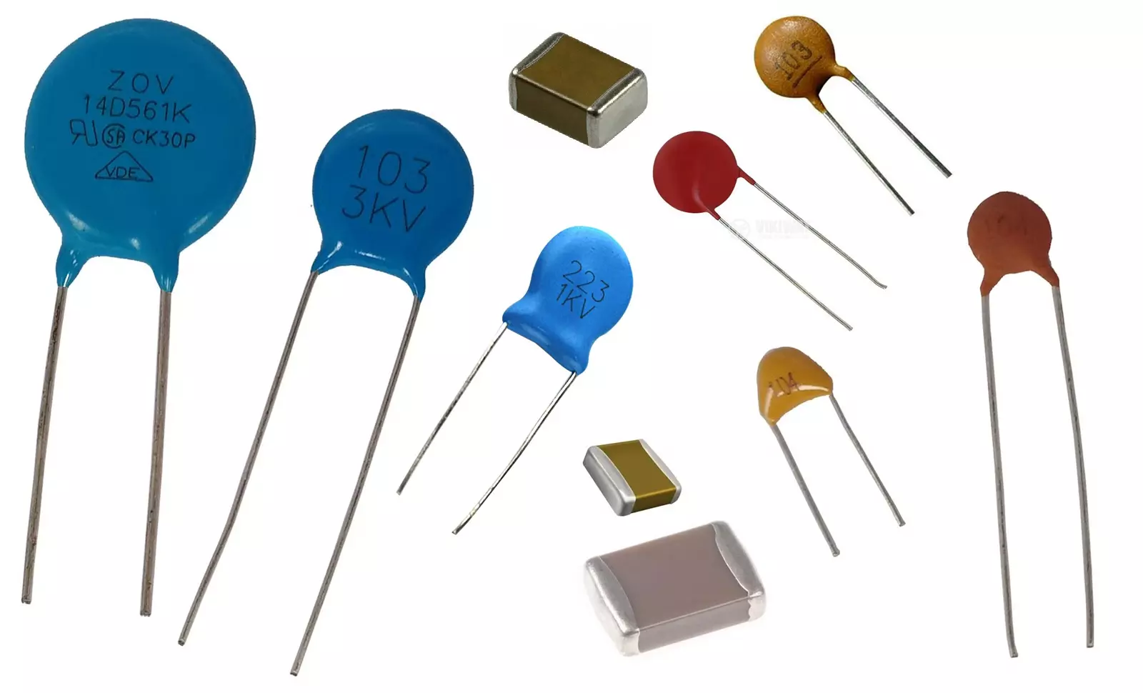
Ceramic Capacitors
Ceramic capacitors are the most widely used non-polarized capacitors. They consist of alternating layers of metal electrodes and ceramic dielectric materials (paraelectric or ferroelectric).
Electrical Characteristics
- Capacitance range: 0.1 pF to several 100 µF (most common: 1 pF–1 µF for Class I, 100 nF–100 µF for Class II/III)
- Voltage rating: 10 V to >20 kV (common: 16–630 V)
- Temperature range:
- Class I (C0G/NP0): −55°C to +125°C
- Class II (X7R/X5R): −55°C to +85/125°C
- Class III (Y5V/Z5U): −30°C to +85°C
- Insulation resistance: Typically >10 GΩ (lower for high-K formulations or large values)
- Frequency performance:
- Class I: Excellent into GHz range, ultra-low loss
- Class II: Good for HF–low VHF
- Class III: Poor for high-frequency use
Construction and Common Shapes
- Metal layers: Nickel or Copper
- Dielectric thickness: as low as 0.5 µm
- Encapsulated with ceramic or epoxy for moisture protection
- Ceramic Disc Capacitors – Single ceramic disc with through-hole terminals
- MLCC (Multilayer Ceramic Chip Capacitors) – Rectangular SMD type with dozens to hundreds of alternating layers
Ceramic Capacitor Classes
Ceramic capacitors are categorized into 4 classes based on dielectric composition and electrical behavior.
1 Class 1 Ceramic Capacitors
- Dielectric: Paraelectric materials (e.g., Titanium Dioxide – TiO₂)
- Most accurate and stable
- Lowest losses
- No aging, capacitance independent of applied voltage
Advantages:
- Excellent frequency response
- Extremely stable with temperature
- Ideal for RF and resonant circuits
Disadvantages:
- Low volumetric efficiency → low capacitance
Applications:
- Oscillators
- Resonance tanks
- Precision timing circuits
2 Class 2 Ceramic Capacitors
- Dielectric: Ferroelectric materials with additives
- Higher permeability → higher capacitance in smaller volume
- Lower stability and accuracy
Characteristics:
- Capacitance varies with voltage and temperature
- Aging over time
- Good volumetric efficiency
Applications:
- Decoupling
- Bypass
- Coupling circuits
Most common types: X7R, Y5V, Z5U
3 Class 3 & Class 4 Ceramic Capacitors
- Very high dielectric constants → high capacitance
- Worst electrical parameters among all classes
- Highly unstable over temperature and voltage
- Significant aging
Status: Class 3 and 4 are considered obsolete, replaced by improved Class 2 materials.
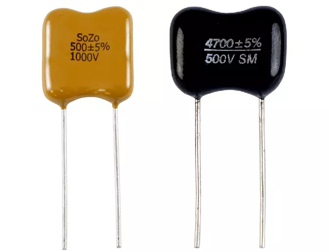
Mica Capacitors
Mica capacitors use natural or synthetic mica sheets as the dielectric. They are known for extremely high stability, very low losses, and excellent precision. Mica is a layered mineral that provides exceptional electrical properties even at high frequencies and temperatures.
Electrical Characteristics
- Capacitance range: 1 pF to 10 nF
- Voltage rating: 50 V to >5 kV
- Temperature range: −55°C to +125°C
- Insulation resistance: Very high, often >100 GΩ
- Frequency performance: Excellent from HF up to UHF
Key Features
- Exceptional temperature stability
- Very low dielectric losses (low dissipation factor)
- High Q factor — ideal for RF and precision circuits
- Low dielectric absorption
- High voltage strength
- Long-term stability and reliability
- Excellent performance at high frequencies (HF/VHF/UHF)
Mica capacitors come in two primary types:
- Silvered Mica Capacitors
- Clamped/Stacked Mica Capacitors
Silvered Mica Capacitors
- Mica sheets are coated with silver electrodes
- Layers are stacked and epoxy-sealed
- Excellent precision: typical tolerance ±1% to ±5%
- Capacitance values usually between 1 pF and 10 nF
- Very low temperature coefficient (typically ±50 ppm/°C)
Applications
- RF oscillators
- Filters (IF, HF, VHF)
- Resonant LC tanks
- High-frequency timing networks
- Precision capacitor networks
- Test equipment requiring stable capacitance
Clamped/Stacked Mica Capacitors
- Mica sheets stacked with metal foils
- Used in older high-voltage constructions
- High surge voltage capability
- More robust but larger than silvered mica types
Applications
- High-voltage RF systems
- Vintage radio equipment
- Industrial HV pulse circuits
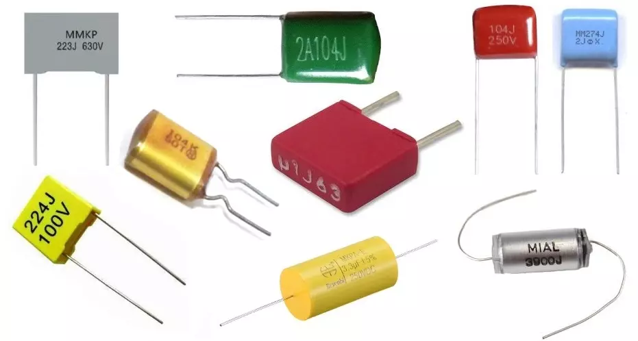
Film Capacitors
Film capacitors use plastic or paper films as dielectrics and are known for exceptional reliability, low losses, and long service life. They are widely used in AC, DC, high-voltage, and high-frequency systems.
Electrical Characteristics
- Capacitance range: ~1 pF to several hundred µF (common: 10 pF–1 µF)
- Voltage rating: 50 V to >400 kV (common: 50–1000 V)
- Temperature range: −55°C to +105°C (up to 125°C for PEN/PPS; ~200°C for PTFE)
- Insulation resistance: Very high, typically >10 GΩ (PP/PTFE highest)
- Frequency performance: Excellent from low frequency through HF, VHF, and into UHF; very low ESR and dissipation factor
Key Features
- High insulation resistance and very low leakage current
- Extremely low ESR and dissipation factor
- Excellent temperature, voltage, and frequency stability
- High voltage capability (from a few volts up to hundreds of kV)
- Self-healing capability in metallized versions
- Long operational lifespan (often 100,000+ hours)
- Available in both AC and DC rated versions
Film capacitors are built in two major construction types:
- Metallized Film Capacitors – thin metal coating on the dielectric
- Film/Foil Capacitors – solid metal foils with dielectric layers
1 Metallized Film Capacitors
- Dielectric film coated with thin aluminum or zinc
- Self-healing removes shorted areas, increasing reliability
- Smaller size compared to film/foil types
- Capacitance values up to about 100 µF are common
- Available in PET, PP, PEN, PPS, and polycarbonate dielectrics
Typical Applications
- Snubber networks
- DC link capacitors (SMPS, inverters)
- General AC filtering
- Audio crossovers
- High-frequency EMI suppression
2 Film/Foil Capacitors
- Solid metal foils separated by dielectric film
- Excellent surge and pulse current capability
- Mechanically robust and durable
- Larger and heavier than metallized types
- Very low inductance available in stacked-film variants
Typical Applications
- Pulse discharge circuits
- High-current snubbers
- Audio signal coupling with minimal distortion
- High-frequency AC filtering
3 Paper Film Capacitors
- Oil-impregnated paper or metallized paper used as dielectric
- High mechanical strength and breakdown resistance
- Older versions absorbed moisture; modern oil-sealed types are improved
- Often combined with polypropylene for higher stability
Applications
- High-voltage AC distribution systems
- Power factor correction
- Ripple filtering in industrial power supplies
4 Polyester (PET/Mylar) Capacitors
- Dielectric: Polyethylene Terephthalate (PET)
- High volumetric efficiency → compact designs
- Moderate temperature stability
- Good moisture resistance
- Temperature range: −55°C to 125°C
- Voltage: up to about 60 kV for special high-voltage versions
- Most common general-purpose film capacitor
Applications
- Coupling/decoupling
- General filters
- SMD small-value capacitors
- Analog signal circuits
5 Polypropylene (PP) Film Capacitors
- Superior dielectric with very low losses
- Highly stable over voltage, frequency, and time
- Excellent for AC and pulse applications
- Max temperature: 105°C
- Max operating frequency: ≈100 kHz
- Voltage rating: up to ≈400 kV (power film types)
Applications
- AC motor run capacitors
- Power factor correction banks
- Induction heating resonant tanks
- High-voltage pulse circuits
- DC link filtering in inverters and SMPS
6 Polyethylene Naphthalate (PEN) Capacitors
- High-temperature performance: up to 175°C
- Better stability than polyester
- Lower capacitance density than PET
- Available only in metallized form
Applications
- SMD electronics
- Compact decoupling networks
- Filtering in high-temperature devices
7 Polyphenylene Sulfide (PPS) Capacitors
- Highly stable electrical characteristics
- Withstands up to 200–270°C (dielectric limit)
- Excellent frequency stability
- Reliable for precise timing and tuning circuits
- More expensive than PET or PP
Applications
- High-temperature circuits
- Precision RC timing
- Audio signal-grade filtering
- Stable frequency-dependent networks
8 PTFE (Teflon) Film Capacitors
- Dielectric: Polytetrafluoroethylene
- High temperature rating (≈200°C or higher)
- Extremely low loss tangent
- Very stable under RF conditions
- Unaffected by humidity and aging
- Bulky and expensive
Applications
- Aerospace electronics
- Military RF systems
- High-frequency instrumentation
- Precision analog circuits
9 Polystyrene (PS) Capacitors
- Excellent long-term stability
- Very low dielectric absorption (good for integrators)
- Low maximum temperature (≈85°C)
- Limited availability today
Applications
- Low-frequency analog circuits
- Precision integrators and filters
- Lab-grade measurement systems
10 Polycarbonate (PC) Film Capacitors
- Exceptionally stable from −55°C to +125°C
- Low dielectric losses
- Good long-term reliability
- Better than PET but lower performance than PTFE
Applications
- Precision timing circuits
- High-reliability filtering
- Stable analog measurements
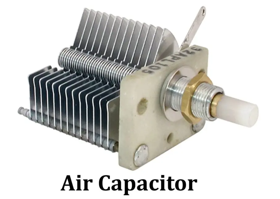
Air Capacitors
Air capacitors use air as the dielectric between the plates. Because air has a dielectric constant close to 1 and very low loss, these capacitors are especially useful in high-frequency applications. Many air capacitors are variable, changing capacitance by rotating interleaving metal plates. They are commonly used in tuning circuits for radio receivers and transmitters.
Electrical Characteristics
- Dielectric: Air (εr ≈ 1)
- Capacitance Range: Typically a few pF to low nF
- Voltage Rating: High
- Temperature Stability: Good (can be affected by humidity)
- Loss Factor (tan δ): Exceptionally low
- Leakage Current: Very low
- Frequency Response: Excellent for RF and microwave
- ESR / Q: Very low ESR, high Q
Key Features
- Often adjustable (variable capacitors)
- No dielectric aging or drift
- Very low loss at high frequencies
- Simple, clean dielectric material
- Physically larger for a given capacitance and sensitive to dust/humidity
Applications
- RF tuning circuits (radios, receivers, transmitters)
- Antenna tuners and impedance-matching networks
- Resonant tank circuits and oscillators (HF/VHF)
- Test equipment and variable-capacitor adjustments
- Vintage radio restorations
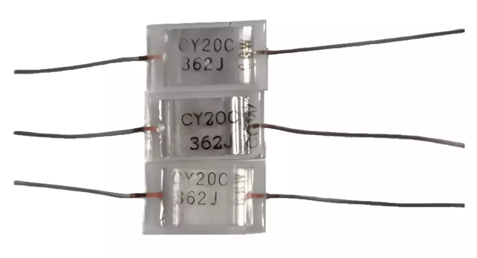
Glass Capacitors
Glass capacitors use glass as the dielectric, offering very high stability, low loss, and excellent environmental resistance. They provide outstanding long-term stability and reliability, making them suitable for precision and high-reliability applications. Due to higher cost, they are used where performance is critical.
Electrical Characteristics
- Dielectric: Glass
- Capacitance Range: pF to several µF
- Voltage Rating: Very high
- Temperature Stability: Excellent (often −55°C to +200°C or higher)
- Loss Factor: Extremely low across wide frequencies
- Leakage Current: Extremely low
- Frequency Response: Excellent for precision and RF
- ESR: Very low
- Long-Term Stability: Minimal capacitance drift
Key Features
- Highly reliable with long operational life
- Resistant to moisture, shock, and radiation
- Very stable over temperature, voltage, and time
- High precision and low noise
- Suitable for harsh and high-temperature environments
- More expensive than ceramic or film capacitors
Applications
- Aerospace electronics and satellites
- Military and mission-critical systems
- High-precision filters and timing circuits
- High-temperature instrumentation
- RF and microwave electronics
- Radiation-hard electronics (nuclear, scientific)
- Medical instrumentation requiring high stability
Advantages of Non-Polarized Capacitors
- Can handle AC signals (no polarity restriction)
- Stable capacitance across temperature and voltage
- Low ESR and low dissipation factor → good for high-frequency use
- Excellent reliability and long lifespan
- Low distortion → ideal for audio paths
- High insulation resistance and leakage current is very low
- Good pulse handling capability (especially polypropylene film)
- Operates at higher voltages compared to electrolytics
- High dielectric strength
- No risk of reverse-polarity damage
Disadvantages of Non-Polarized Capacitors
- Larger physical size compared to electrolytics of same capacitance
- Lower capacitance values available (typically microfarads and below, except specialized types)
- Can be more expensive than polar electrolytics
- Not suitable for very large energy storage (hundreds–thousands of µF)
- Some types (e.g., polyester) have non-linearities at high frequencies
- Bulkier for power-factor correction units compared to optimized electrolytics
- Limited very-high-temperature operation compared to ceramic C0G/NP0
Applications of Non-Polarized Capacitors
1. AC and Power Circuits
- Power factor correction
- AC motor run capacitors
- AC line filtering (X/Y safety capacitors)
- Snubber circuits for power switches
- EMI/RFI suppression
- Capacitive AC droppers
- HF filtering in inverters
2. Audio and Music Systems
- Speaker crossover networks
- Tone control filters
- Audio coupling and decoupling
- Bypass capacitors in analog audio
- Microphone/preamp coupling
- Passive guitar/bass tone circuits
- Equalizers and audio smoothing networks
3. RF and Communication
- Tuned LC circuits
- Oscillators (Colpitts, Hartley, crystal load caps)
- RF/microwave filters
- Antenna matching networks
- RF bypassing
- RF transmitter/receiver front-end networks
4. Power Electronics
- SMPS resonant circuits
- DC link filtering (film capacitors)
- High-voltage pulse circuits
- Snubber networks for IGBT/MOSFET drivers
- Resonant LLC converter tanks
- Energy discharge for welding/lasers
- Inverter output filters
5. Timing and Control Circuits
- RC timing circuits
- Sample-and-hold stages
- VCO timing elements
- Integrators/differentiators
- Precision timing (low-drift film capacitors)
- Phase-shift oscillators
6. Industrial and High-Voltage
- Induction heating resonant tanks
- HV inverter circuits
- HV measurement systems
- Pulse forming networks (PFN)
- Marx generator stages (special HV film capacitors)
- Defibrillator/pulse discharge systems
Conclusion
Non-polar capacitors are indispensable in both low-power electronics and high-voltage industrial systems. Their polarity-free operation, high stability, low loss, and wide temperature capability make them suitable for a broad range of applications from audio and RF circuits to power factor correction and SMPS.
Each type, ceramic, mica, and film offers unique advantages. Understanding their internal structure, dielectric materials, and performance characteristics helps engineers choose the right capacitor for optimal circuit performance.
Types of Capacitors with Symbol, Classification and Applications
Polarized Capacitors – Symbol, Types, Construction, Working and Applications
What is Coupling Capacitor, Construction, Working & Applications
Difference Between Coupling, Decoupling, and Bypass Capacitors
Ceramic vs Electrolytic Capacitor: Key Differences and Applications
