In this article, you will learn to build LM3915 battery voltage level indicator. The LM3915 is a popular integrated circuit (IC) used in projects that require visual feedback on voltage levels. It’s widely applied in devices like battery monitors, audio level meters, and power supply indicators. This IC lights up a series of LEDs to show different voltage levels, making it easy to track changing voltages at a glance.
What is LM3915?
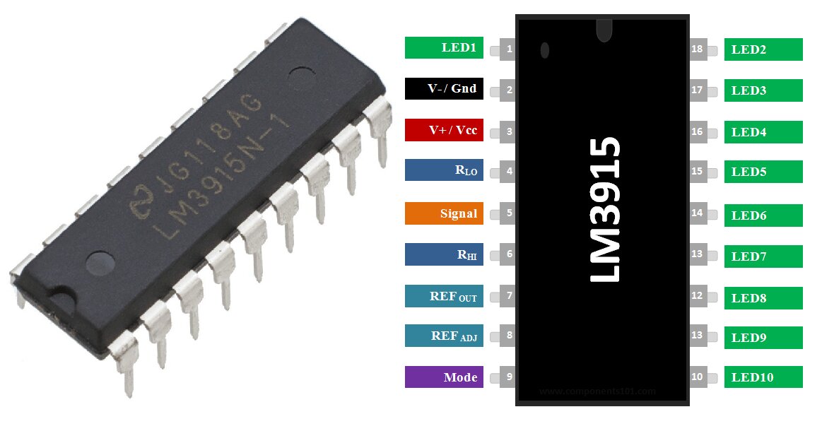
The LM3915 is an easy-to-use IC that drives LED displays to show the voltage level of an input signal. It features a logarithmic scale, meaning each step (or LED) represents a 3 dB increase, which makes it ideal for applications where you need to track voltages over a wide range. You can set the IC to light either a single LED at a time (dot mode) or illuminate all the LEDs progressively as the voltage increases (bar mode). It also allows you to easily control the current through the LEDs and adjust the reference voltage to match your specific needs.
Key Features of LM3915:
- Logarithmic Voltage Scaling: The LM3915 tracks voltage on a logarithmic scale, with a 3 dB step between each LED, making it great for applications where voltage changes exponentially.
- Adjustable Reference Voltage: You can modify the reference voltage to set the range of voltages that the LEDs will display.
- Dot/Bar Display Mode: Choose between dot mode (only one LED is on at a time) or bar mode (all LEDs up to the current voltage level light up).
- LED Current Control: You can adjust the LED current without needing additional resistors.
- Wide Operating Voltage: The IC operates with supply voltages between 3V and 25V, making it flexible for many projects.
LM3915 IC Working:
The LM3915 compares an input voltage to 10 internal reference voltages, turning on the corresponding number of LEDs as the voltage increases. Each LED represents a step on the voltage scale, lighting up when the input voltage crosses a threshold. You can set the range of these reference voltages using resistors connected to the RHI (pin 6) and RLO (pin 4) pins. This allows the LM3915 to be adjusted for different applications, whether you’re measuring small or large voltage ranges.
LM3915 Battery Level Indicator Circuit Diagram:
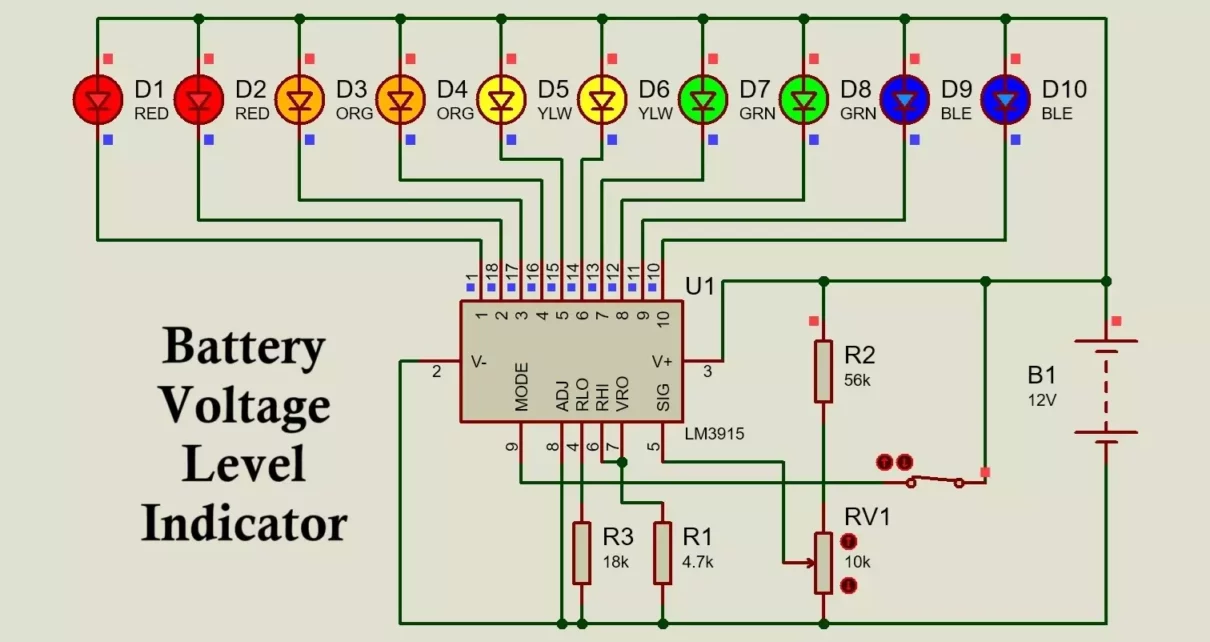
Here’s a typical circuit you can build using the LM3915 to display voltage levels: 
Components:
- LM3915 IC: The brain of the circuit, which drives the LED display.
- 10 LEDs: These LEDs light up based on the voltage level we have chosen a pair of Red, Orange, Yellow, Green, and Blue LEDs.
- Resistors: To set the reference voltage 56K, 18K, 4.7K & 10K potentiometer.
- Capacitor: A small capacitor stabilizes the reference voltage (optional).
- Voltage Input: This is the signal whose voltage level you want to measure here we have our 12V battery.
Circuit Connections:
- LED Connections (Pin 1 & 10 to 18): Each of these output pins connects to one LED. As the voltage increases, more LEDs light up.
- Reference Out (Pin 7): This pin is used to control brightness of LED lights.
- Power Supply (Pin 2, 3): Connect this pin to the power supply (between 3V and 25V).
- Mode Selection (Pin 9): This pin allows you to switch between dot mode (one LED lights at a time) and bar mode (all LEDs up to the voltage level light up).
- Reference Voltage Pins (Pin 4 & Pin 6): These pins control the minimum and maximum voltage levels the LM3915 will detect, set by external resistors.
- Signal Input (Pin 5): Receives the analog voltage input that the IC will measure and display.
Here is the PCB of above circuit


Here is how it will look when fully assembled

Download the above battery voltage indicator circuit files from here,
Building the Circuit on breadboard:
- Place the LM3915: First, place the LM3915 IC on your breadboard, ensuring the pinout matches your wiring plan.
- Connect the LEDs: Attach each of the 10 LEDs to the output pins (Pin 1 & Pin 10 to 18) of the LM3915.
- Adjust the Reference Voltage: Use two resistors to connect the RHI (Pin 6) and RLO (Pin 4) pins to set the reference voltage range. Short pin 6 and 7 This will define the minimum and maximum voltages for the display.
- Voltage Source: Supply power to the IC by connecting Pin 2 and 3 to your power source. Make all the connections as shown in the Circuit.
- Set the Display Mode: Use Pin 9 to select either dot mode (when low) or bar mode (when high) depending on your preference.
Monitoring a 12V Lead-Acid Battery:
Let’s say you want to monitor the voltage level of a 12V lead-acid battery using the LM3915. You can configure the circuit so that each LED lights up at a specific battery voltage level:
- Low Voltage (10.5V): When the battery voltage is 10.5V, only the first LED will light up, indicating a low charge.
- Fully Charged (12.8V): When the battery voltage reaches 12.8V, all LEDs will light up, signaling that the battery is fully charged.
Here is a video for your better understanding of 12V battery level indicator:
By adjusting the resistance on potentiometer, you can fine-tune the circuit to reflect the voltage range of your battery. This way, the LM3915 provides a clear and immediate visual indication of the battery’s charge status.
How the Circuit Operates:
- Low Voltage Condition: When the input voltage is below the reference voltage set by your resistors, no LEDs will light up.
- Increasing Voltage: As the voltage increases and crosses the first reference level, the first LED lights up. As the voltage continues to rise, more LEDs will turn on.
- Full Scale Voltage: When the voltage reaches the maximum reference level (set by the RHI pin), all 10 LEDs will light up in bar mode or the highest LED in dot mode.
Advantages of Using the LM3915 IC:
- Simple and Effective: It offers a straightforward solution to monitor voltage without complex circuitry or microcontroller programming.
- Wide Range: The logarithmic response makes it suitable for applications where the input voltage covers a large dynamic range.
- Customizable: You can easily adjust the reference voltage and LED current, allowing the circuit to fit many different applications.
- Dot/Bar Flexibility: Switching between dot and bar mode provides flexibility depending on whether you prefer a simple or a detailed visual output.
Applications of LM3915 IC:
1. Audio Level Indicators (VU Meters)
Audio signal visualization: Designers commonly use the LM3915 to create (volume unit) VU meter circuit for audio equipment. This IC displays the audio signal level using LEDs, where each LED represents a specific dB level, providing a visual representation of audio strength. Stereo systems and amplifiers: Users employ it to show audio levels in home audio systems, guitar amplifiers, and mixing consoles. Equalizer display: Engineers can use it in audio graphic equalizers to show the power level of specific frequency bands.
2. Battery Voltage Level Indicators
Battery charge indicators: The LM3915 displays the voltage level of a battery or power supply system, indicating how much charge remains. Power status in portable devices: Designers commonly use it in portable devices to provide a visual representation of battery health (e.g., in laptops, electric vehicles, or portable speakers).
3. Power Supply Monitoring
Power supply units (PSUs): Engineers utilize the LM3915 IC to monitor voltage levels in power supply circuits, ensuring the system operates within safe parameters. Uninterruptible Power Supplies (UPS): This IC shows the status of input and output voltage levels, ensuring stable power delivery.
4. Temperature Level Monitoring
Thermal systems: The LM3915 displays temperature levels using a temperature sensor as input. Manufacturers often use it in thermal management systems to indicate overheating or abnormal temperature conditions. Industrial machinery: Technicians visually monitor machinery temperature to ensure safe operation.
5. Pressure Sensors and Environmental Monitoring
Pressure indication: When connected to pressure sensors, the LM3915 indicates pressure levels (e.g., in hydraulic or pneumatic systems). Environmental monitors: Researchers use it in systems that monitor various environmental factors like air quality and gas concentration.
6. Current Level Indicators
Current flow monitors: In applications where visualizing current flow is essential, the LM3915 indicates whether the current is within the desired range. Overcurrent protection: By visualizing current levels, it helps provide early warnings for overcurrent situations.
7. Signal Strength Meters
RF and communication systems: Engineers use the LM3915 to display signal strength in RF (radio frequency) communication systems like radios, transceivers, and antenna systems. Wi-Fi signal meters: It also represents the strength of Wi-Fi or wireless communication signals.
8. Light Intensity Meters
Photodiode sensors: Designers combine the LM3915 with light sensors (e.g., photodiodes) to visually display light intensity in lux meters or other photometric instruments.
9. Medical Equipment
Heartbeat monitors: In certain medical equipment, the LM3915 displays the heart rate or other biological signals. Respiratory monitoring: It helps indicate patients’ respiratory activity by displaying relevant data visually.
10. Fuel Level Indicators
Fuel tank monitoring: In automotive applications, the LM3915 displays the fuel level in a tank, providing a visual indication of how full or empty the tank is.
11. Motor Speed Indicators
Tachometers: The IC operates in tachometer applications to display the speed of a motor or engine, useful in automotive or industrial settings.
12. Brightness Level Control
LED dimmers: Designers use it for LED brightness control applications, where varying voltage levels convert into visual LED displays for brightness indication.
13. Alarm Systems
Security systems: This IC visually represents sensor activity in alarm systems, indicating whether the system is active or if certain threshold levels have been exceeded. Fire safety and detection systems: The LM3915 indicates the levels of smoke or hazardous gas present in the air.
14. Frequency Response Visualization
Oscilloscope-like displays: Engineers use the LM3915 in frequency response analysis to create a visual representation of a signal’s amplitude versus frequency.
Conclusion:
The LM3915 LED voltage level indicator is easy-to-use for visual voltage monitoring. With its flexible design and simple setup, it’s ideal for applications ranging from battery monitors to audio meters and power supply indicators. LM3915 IC is useful in any application where visual representation of an analog signal (such as voltage, current, pressure, or temperature) is needed. By carefully selecting the reference voltage and configuring the LEDs, you can create a custom voltage display that fits your specific needs. Whether you’re an electronics hobbyist or working on a more advanced project, the LM3915 makes voltage monitoring simple, efficient, and visually intuitive.
LM3915 Based LED VU Meter Circuit Diagram And Working
