A Regulated Power Supply Block Diagram represents the working principle of a linear regulated power supply, which provides a stable DC output voltage. Unlike switching power supplies, linear regulators use transformers, rectifiers, and voltage regulators to ensure smooth voltage. A Linear Regulated Power Supply Circuit Diagram illustrates its detailed design. These power supplies are preferred in applications requiring low noise and minimal ripple, such as industrial electronics, communication devices, and precision instrumentation where clean and stable DC voltage is necessary.
Working Principle of Linear Regulated Power Supply
A linear regulated power supply works by converting AC voltage into a steady DC voltage using rectification, filtration, and voltage regulation. The voltage regulator ensures that the output remains constant even if the input voltage or load conditions change. The key feature of a linear regulator is its simplicity and ability to provide a clean, low-ripple DC output.
Steps Involved in Voltage Regulation:
- Step-down transformation: Reduces the AC mains voltage to a lower level suitable for rectification.
- Rectification: Converts AC voltage into pulsating DC using diodes arranged in a bridge or full-wave rectifier configuration.
- Filtering: Removes AC components from the rectified voltage using large-value capacitors.
- Regulation: Maintains a constant voltage output despite changes in input voltage or load fluctuations.
Block Diagram of Linear Regulated Power Supply
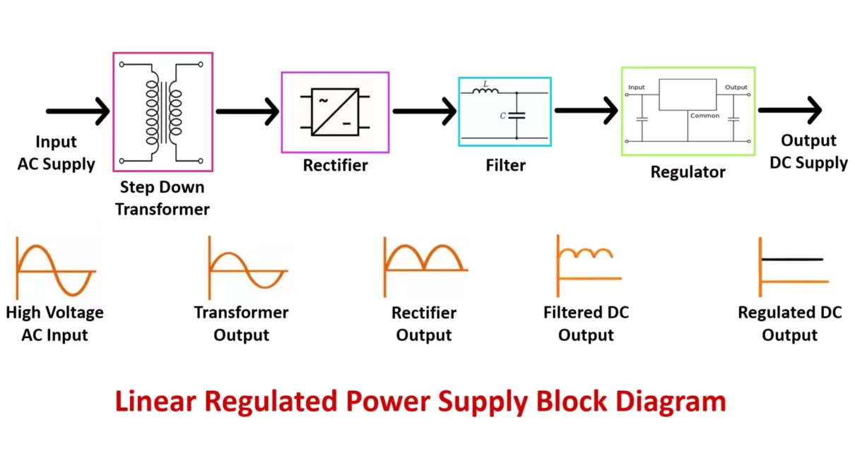
Below is the basic block diagram of a linear regulated power supply:
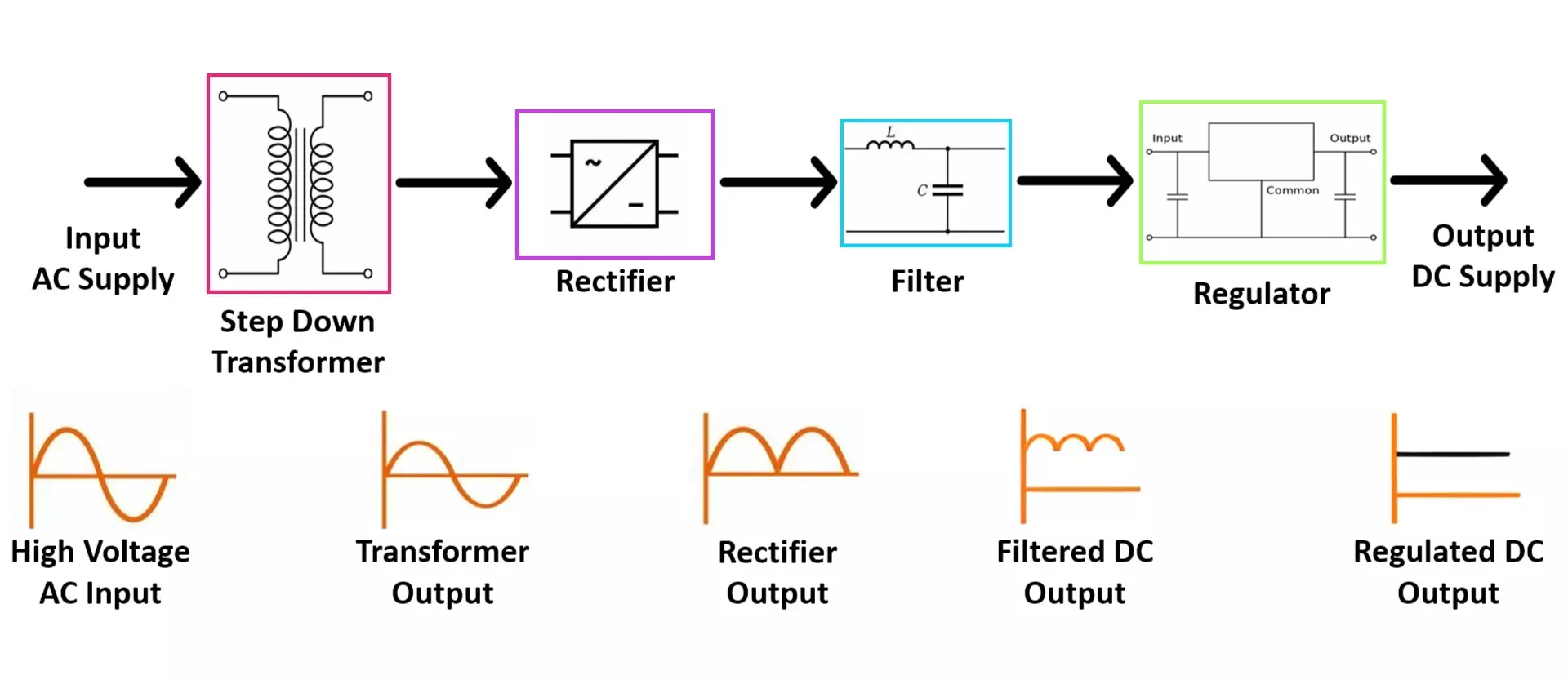
Explanation of Regulated Power Supply Block Diagram
1. AC Input
- The power supply takes an Alternating Current (AC) input from the mains supply (e.g., 120V or 230V AC).
- This AC voltage is usually at a high voltage level and needs to be reduced to a suitable level.
2. Transformer
- The transformer is used to step down the high-voltage AC from the mains to a lower AC voltage.
- It consists of a primary winding, secondary winding, and a magnetic core.
- The output voltage depends on the turns ratio of the transformer.
- If isolation is needed, the transformer ensures electrical separation between the input and output.
3. Rectifier
- The rectifier converts the AC voltage from the transformer into pulsating DC.
- There are different types of rectifiers:
- Half-wave rectifier (Uses one diode, inefficient)
- Full-wave rectifier (Uses a center-tapped transformer and two diodes)
- Bridge rectifier (Uses four diodes, best for efficiency)
- A bridge rectifier is commonly used because it provides full-wave rectification without requiring a center-tapped transformer.
4. Filter
- The rectified voltage is still pulsating DC and needs to be smoothed.
- A capacitor filter is used to remove the ripples.
- The capacitor charges when the voltage increases and discharges when the voltage drops, creating a more stable DC voltage.
- Additional filtering components like inductors and voltage stabilizers can be used for better ripple suppression.
5. Voltage Regulator
- The voltage regulator ensures a constant DC output voltage despite variations in load current or input voltage.
- Types of voltage regulators:
- Zener Diode Regulator – Uses a zener diode for simple regulation.
- Linear Voltage Regulators (e.g., 78XX, LM317) – Provides stable voltage but dissipates excess energy as heat.
- Series Pass Transistor Regulator – Uses a transistor in series with the load for better control.
- Drawback: Linear regulators are inefficient for high-power applications since they convert excess energy into heat.
6. DC Output
- The final output is a stable DC voltage that can be used to power electronic circuits.
- Common output voltages: 5V, 12V, 24V, etc.
Linear Regulated Power Supply Circuit Diagram
3V to 35V, 5A Linear Power Supply Using LM317 and TIP3055
A linear power supply is essential for applications that require a stable and adjustable DC voltage. In this article, we will design a 3V to 35V, 5A linear power supply using the LM317 voltage regulator and a TIP3055 power transistor. The LM317 provides precise voltage regulation, while the TIP3055 transistor boosts the output current capacity.
Circuit Components & Selection
- Transformer (30V AC, 6A): Steps down the mains 230V AC to 30V AC.
- Bridge Rectifier (10A, 100V diodes, e.g., 1N5408 or KBPC1010 module): Converts AC to pulsating DC.
- Filter Capacitors:
- 4700µF, 63V for primary DC filtering.
- 0.1µF capacitor for noise suppression.
- LM317 Voltage Regulator: Controls output voltage precisely.
- TIP3055 Power Transistor: Boosts current capacity to 5A.
- BD139 Transistor: Controls the base current of TIP3055 for improved regulation.
- Resistors:
- R1 (10kΩ): Limits current to LED indicator.
- R2 (220Ω): Connected between output of 1N4007 diode and adjust pin of LM317.
- Diodes:
- 1N4007: Connected to the output of LM317 for voltage feedback.
- Potentiometers:
- 10kΩ (for LM317 voltage adjustment).
- Another potentiometer at the base of BD139, connected to both collector and emitter, controls current regulation.
- Capacitors:
- 0.1µF capacitor across 1N4007 output for stability.
- 47µF, 63V capacitor at the emitter of TIP3055 for output smoothing.
- Voltage & Current Measurement:
- Amp Meter in series with the output.
- LM7805 Voltage Regulator: Powers the Volt-Amp Meter.
- Voltage is measured from the 1N4007 output.
- Primary Fuse (2A Slow-Blow, 230V AC): Protects transformer from overload.
- Secondary Fuse (6A Slow-Blow, DC Output): Protects the DC circuit from short circuits.
- Heat Sink: Large for LM317, TIP3055, and BD139 to prevent overheating.
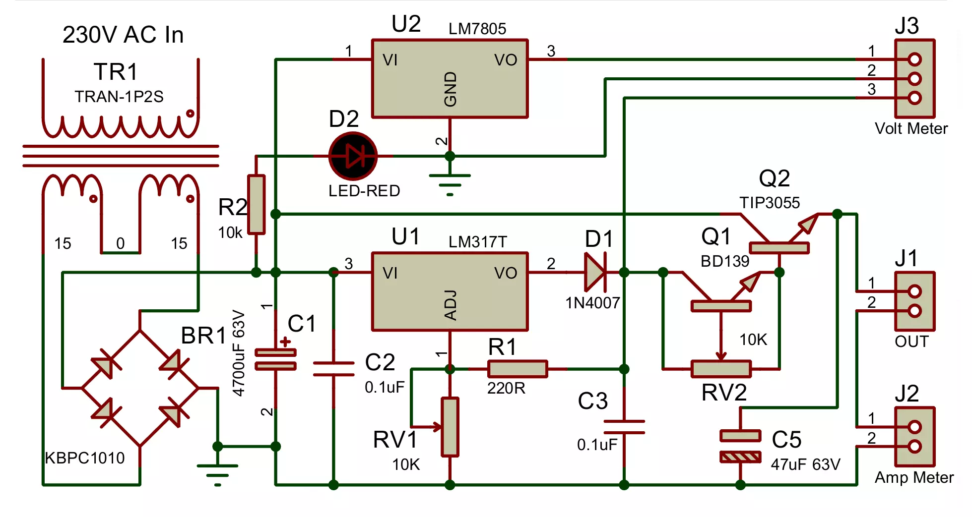
Circuit Diagram and Connections
- Transformer: Connect the primary side to 230V AC mains, and the secondary side provides 30V AC.
- Bridge Rectifier: Connect the AC output from the transformer to the AC terminals of the bridge rectifier. The rectifier’s positive and negative terminals provide pulsating DC.
- Filter Capacitors:
- Connect 4700µF, 63V capacitor across the rectified DC output for primary filtering.
- Connect 0.1µF capacitor for noise suppression.
- LM317 Regulator: Connect the filtered DC voltage (42V DC) to the input pin of the LM317.
- Voltage Adjustment Circuit:
- Connect one end and adjust pin of the 10kΩ potentiometer to the adjustment pin of LM317. Connect the other end of the potentiometer to the ground.
- Connect R2 (220Ω) between the output of 1N4007 diode and the adjust pin of LM317.
- Place 0.1µF capacitor across the 1N4007 output for stability.
- Current Control Circuit:
- Use a BD139 transistor with a potentiometer at its base.
- The potentiometer is connected to both the collector and emitter.
- The emitter of BD139 controls the base of TIP3055 to regulate current.
- Current Boosting with TIP3055:
- Connect the collector of TIP3055 to the positive supply from filter capacitor.
- Connect the emitter of TIP3055 directly to the output.
- Output Capacitor: Connect 47µF, 63V capacitor across the final output to improve voltage stability.
- Voltage & Current Measurement:
- Connect an Amp Meter in series with the output for current measurement.
- Use LM7805 voltage regulator to power the Volt-Amp Meter.
- Measure output voltage from the 1N4007 output.
- Fuses:
- Primary Fuse (2A, 230V AC) in series with the mains input.
- Secondary Fuse (6A, DC output) in series with the output load.
- Heat Sinks: Attach large heat sinks to LM317, TIP3055, and BD139 to dissipate excess heat.
- Indicator LED: Connect a red LED with a 10kΩ resistor across the filter capacitor for power indication.
Regulated Power Supply Circuit Diagram Explanation
1. AC to DC Conversion
- The 30V AC, 6A transformer steps down the mains 230V AC to 30V AC.
- The bridge rectifier converts AC to pulsating DC.
- The 4700µF capacitor smooths the DC voltage, providing ~42V DC.
2. Voltage Regulation & Current Boosting
- The LM317 regulates the voltage, ensuring an adjustable 3V to 35V DC output.
- The TIP3055 power transistor amplifies current, allowing the circuit to handle 5A load.
- The BD139 transistor controls the base drive of TIP3055, enabling better current regulation.
- R2 (220Ω) and 1N4007 diode improve voltage feedback stability.
- The 10kΩ potentiometer adjusts the output voltage.
3. Protection & Measurement
- The primary side fuse (2A slow-blow, 230V AC) protects against transformer overload.
- The secondary side fuse (6A slow-blow, DC output) safeguards against short circuits.
- The heat sinks on the LM317, TIP3055, and BD139 dissipate excess heat, ensuring stable operation.
- The Amp Meter measures current, while the Volt-Amp Meter powered by LM7805 displays voltage and current.
- The red LED with a 10kΩ resistor acts as a power-on indicator.
Working of LM317 Linear Regulated Power Supply Circuit
- When the circuit is powered, AC voltage from the transformer is rectified and filtered to provide a steady 42V DC.
- The LM317 regulates the voltage based on the feedback from the 10kΩ potentiometer.
- The BD139 transistor adjusts the base current of TIP3055, controlling output current.
- The TIP3055 transistor acts as a current booster, ensuring up to 5A of output current.
- The output voltage can be adjusted between 3V to 35V using the potentiometer.
- The fuses, heat sinks, and current regulation circuit provide overcurrent and thermal protection.
Final Considerations
- Efficiency: Since it is a linear regulator, excess power is dissipated as heat, making it less efficient than a switch-mode power supply.
- Cooling Requirement: Proper heat sinks are essential to prevent thermal shutdown.
- Applications: This power supply is suitable for laboratory testing, battery charging, and powering circuits requiring adjustable DC voltage.
Advantages of Linear Power Supply
- Simple design and easy to implement.
- Low noise and ripple-free DC output.
- Better transient response compared to switching power supplies.
- Suitable for sensitive circuits like audio amplifiers, sensors, and analog measurement systems.
- No switching noise or EMI issues compared to SMPS (Switch Mode Power Supplies).
Disadvantages of Linear Power Supply
- Low efficiency due to heat dissipation in the regulator, making it unsuitable for high-power applications.
- Bulky size due to large transformers and heat sinks.
- Limited output power capability compared to switching power supplies.
- Higher power dissipation, leading to significant energy loss as heat.
Applications of Linear Regulated Power Supply
- Used in laboratory power supplies for testing electronic circuits.
- Powering analog circuits like operational amplifiers, transducers, and medical equipment.
- Audio amplifiers requiring low-noise power sources.
- Battery charging circuits for controlled DC power supply.
- Communication devices, ensuring stable voltage for RF circuits.
- Embedded systems such as microcontrollers and sensors where stability is crucial.
Additional Considerations
Improving Efficiency
Although linear power supplies are less efficient than switching supplies, some techniques can improve performance:
- Using a low-dropout regulator (LDO): Reduces power dissipation by allowing operation with a smaller voltage difference between input and output.
- Implementing a pre-regulator stage: A switching pre-regulator can drop excessive voltage before reaching the linear regulator, improving efficiency.
- Choosing a larger heat sink: Helps in dissipating excess heat and prevents thermal shutdown.
Alternative Voltage Regulators
Apart from LM317, other linear regulators include:
- LM337 (adjustable output voltage in negative 1.2V to 37V)
- 7805, 7809, 7812, 7824 (fixed voltage regulators for 5V, 9V, 12V, 24V output respectively)
- LT1085, LT1083 (low-dropout regulators for improved efficiency)
Difference Between Linear and Switching Power Supply
| Feature | Linear Power Supply | Switching Power Supply |
|---|---|---|
| Efficiency | Low (30-60%) | High (80-95%) |
| Size & Weight | Large & heavy | Compact & lightweight |
| Heat Generation | High (wastes energy) | Low (more efficient) |
| Complexity | Simple, easy to repair | Complex, harder to fix |
| Noise & EMI | Low noise & ripple | High-frequency noise |
| Cost | Cheaper for low power | Costlier but efficient |
Conclusion
A linear regulated power supply is an essential component in many electronic applications where a stable and noise-free power source is required. While they may not be as efficient as switching power supplies, their simplicity, reliability, and low noise make them ideal for various low-power applications. Understanding the working principles and circuit design allows engineers and hobbyists to build reliable power supplies tailored to their specific needs. With careful component selection and design considerations, linear power supplies can provide excellent performance for sensitive electronic circuits.
12V 10A SMPS: Switched Mode Power Supply Circuit – IC DM0565
