The Light Emitting Diode (LED) is one of the most widely used electronic components today, found in everything from indicator lights to full-scale lighting systems. It is a type of diode that converts electrical energy into light energy, offering a highly efficient alternative to traditional bulbs.
Unlike incandescent lamps that rely on heating a filament, LEDs produce light through electroluminescence – a solid-state process that keeps them cool, energy-efficient, and long-lasting.
The first practical visible-light LED was developed in 1962 by Nick Holonyak Jr. at General Electric. His work on light-emitting semiconductors paved the way for modern LED technology.
LEDs are available in various shapes, sizes, and colors, both visible and invisible. Infrared LEDs power devices like remote controls and sensors, while visible-light LEDs are used in home, street, and display lighting – providing a safe, durable, and energy-efficient illumination solution worldwide.
What is an LED?
Light Emitting Diode (LED) is a PN junction semiconductor diode that emits light when a forward current passes through it. Simply put, an LED converts electrical energy directly into light energy.
When the LED is forward biased, electrons from the n-type region and holes from the p-type region move toward the junction and recombine. This recombination releases energy in the form of photons (light particles). The process is known as electroluminescence – the emission of light from a semiconductor material when it is excited by an electric current.
Not all materials can emit light efficiently. For this reason, LEDs are not made from traditional silicon or germanium but from compound semiconductor materials such as Gallium Arsenide (GaAs), Gallium Phosphide (GaP), Gallium Arsenide Phosphide (GaAsP), Indium Phosphide (InP).
The color of the light emitted depends on the band gap of the semiconductor material used – each material releases photons of a specific wavelength corresponding to a particular color.
The ability of a material to emit light when subjected to an electric field is known as electroluminescence – the key property that makes LEDs special.
Symbol and Lead Identification of LED
LED Symbol
The circuit symbol of an LED is similar to that of a normal diode, with one key difference — it includes two small arrows pointing outward from the diode, representing the emission of light energy.
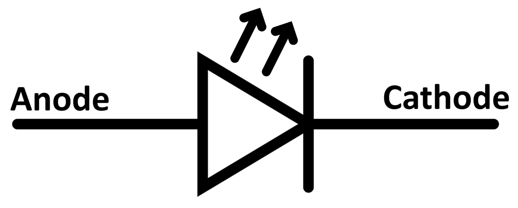
These arrows indicate that light is being radiated from the device when it conducts in the forward direction.
Terminals of an LED
Like any other diode, an LED has two terminals:
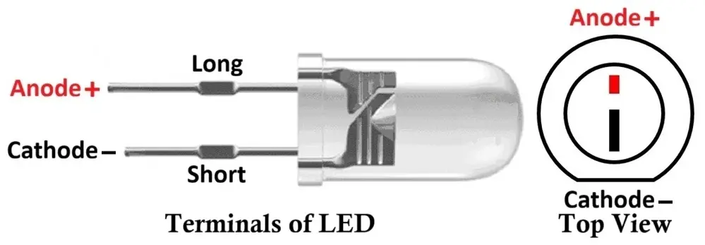
- Anode (+): The positive terminal through which current enters.
- Cathode (−): The negative terminal through which current leaves.
To properly connect an LED in a circuit, you must identify these terminals. The following methods can be used to distinguish between them:
- Lead Length:
- The longer leg is the anode (+).
- The shorter leg is the cathode (−).
- Internal Structure (for transparent LEDs):
- The smaller internal plate indicates the anode.
- The larger internal plate indicates the cathode (as it is also the reflector).
- Flat Spot on Casing:
- Many LEDs have a flat edge near the base of the casing — this marks the cathode side.
- Using a Multimeter:
- In continuity mode, when the LED is forward biased, it will glow faintly or trigger the meter’s buzzer.
- In reverse bias, it will not conduct or glow.
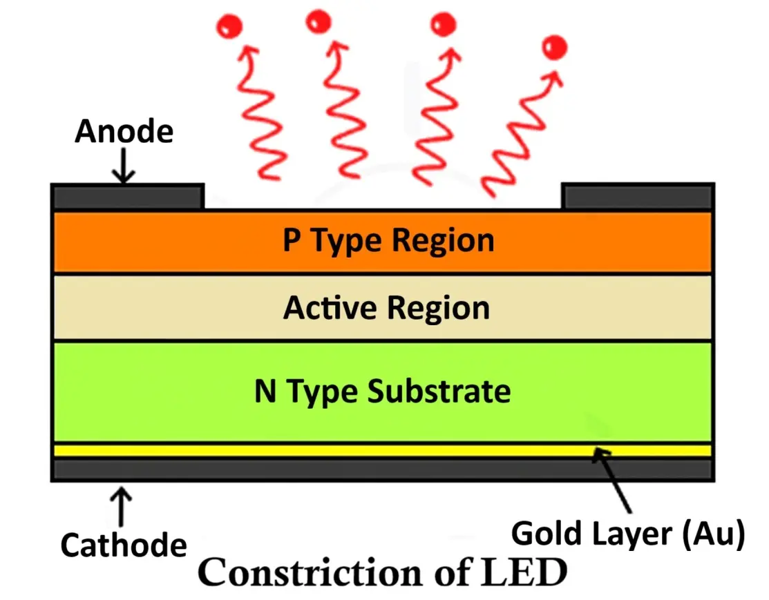
Construction of Light Emitting Diode (LED)
An LED (Light Emitting Diode) is a specially designed semiconductor device composed of multiple layers arranged to optimize light emission and efficiency. The basic structure of an LED includes three primary layers — the P-type semiconductor layer, the N-type semiconductor layer, and the active region (depletion region) between them.
Internal Structure
- P-type Semiconductor Layer:
The P-type layer contains a large number of holes (positively charged carriers) as the majority charge carriers. It is typically placed on the top side of the LED structure since most light emission occurs here when electrons recombine with holes. - N-type Semiconductor Layer:
The N-type layer contains electrons as the majority carriers. It forms the base layer of the LED, providing the required electron supply for recombination within the active region. - Active Region (Depletion Region):
This is the central region between the P-type and N-type layers, containing an equal concentration of electrons and holes. When the LED is forward biased, electrons from the N-region and holes from the P-region move into this active zone and recombine. During this recombination process, energy is released in the form of photons (light) — this phenomenon is known as electroluminescence.
Because the recombination of charge carriers primarily occurs near the P-layer, it is positioned on top to allow maximum light extraction from the surface.
Physical Construction
The P-type and N-type semiconductor materials are fabricated together in thin layers, with the active region sandwiched between them. To facilitate efficient electrical and optical performance:
- The anode contact (positive terminal) is formed along the edge of the P-type layer to allow current to enter and spread evenly.
- The cathode contact (negative terminal) is created using a thin metallic film, usually gold or aluminum, deposited at the bottom of the N-type layer. This reflective layer not only acts as an electrical contact but also helps reflect light emitted downward back toward the top, improving the overall brightness of the LED.
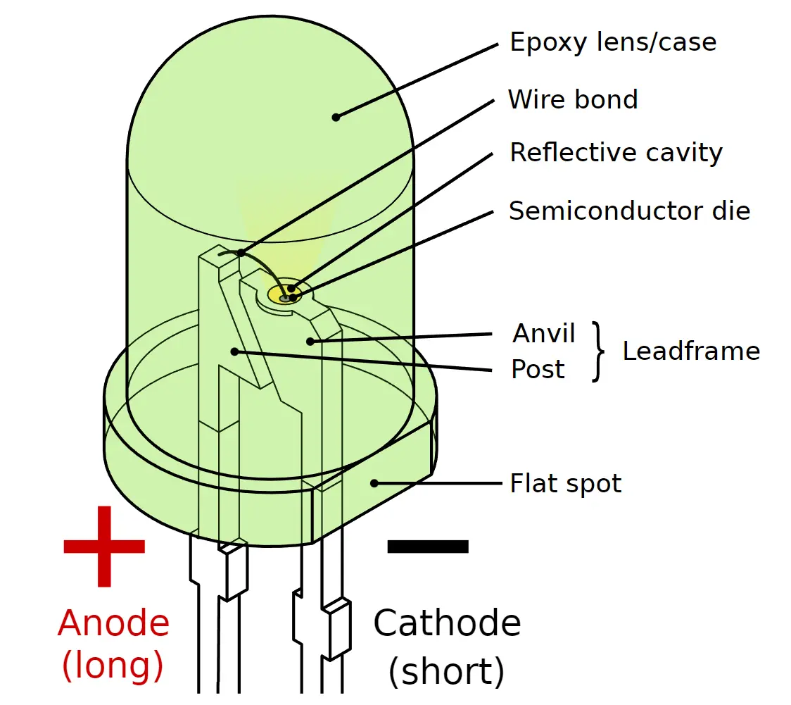
Encapsulation and Lens Design
To protect the semiconductor and maximize light output, the LED chip is enclosed in a transparent epoxy resin or plastic casing. This outer body is often shaped like a dome or lens, which serves several purposes:
- It focuses and directs the emitted light upward.
- It protects the internal semiconductor from mechanical damage and moisture.
- It enhances optical efficiency by minimizing light losses.
In some designs, the dome shape is replaced by triangular, flat-top, or rectangular structures depending on the LED’s intended application – such as display panels, surface-mount indicators, or focused illumination systems.
To further improve efficiency, the bottom layer of the LED is coated with a reflective film (often gold), which redirects light that would otherwise be absorbed or lost back through the top of the LED. Additionally, increasing the surface area of the P-layer enhances the intensity of emitted light.
Light Emission Range
LEDs can emit both visible and invisible (infrared) light, depending on the material composition and the energy band gap.
- Visible light LEDs are used in indicators, display systems, and lighting.
- Infrared LEDs are commonly used in remote control systems, infrared communication, and security sensors.
Materials Used in LED Manufacturing
Traditional semiconductor materials like silicon (Si) and germanium (Ge) are unsuitable for LEDs because they primarily release energy as heat instead of light during recombination.
Instead, LEDs use compound semiconductors that emit energy in the form of photons, such as:
| Semiconductor Material | Color of Emitted Light | Common Application |
|---|---|---|
| Gallium Arsenide (GaAs) | Infrared (IR) | Remote controls, sensors |
| Gallium Arsenide Phosphide (GaAsP) | Red / Orange / Yellow | Indicators, displays |
| Gallium Phosphide (GaP) | Green | Signal lights |
| Gallium Nitride (GaN) | Blue / White | High-intensity lighting |
| Indium Gallium Nitride (InGaN) | Blue / Green / White | Modern LED lighting systems |
These materials are selected based on their band gap energy, which determines the wavelength (color) of the emitted light.
In essence, the LED is a compact, solid-state light source designed for maximum efficiency and durability. Every part of its construction — from the choice of semiconductor material to the reflective base and epoxy lens — plays a crucial role in ensuring that the maximum amount of light is emitted while minimizing heat generation and power loss.
Working Principle of Light Emitting Diode (LED)
The Light Emitting Diode (LED) operates on the same basic principle as a PN junction diode, with one major distinction – it emits light when current passes through it in the forward bias direction.
In forward bias, the anode of the LED is connected to the positive terminal of the power supply, and the cathode is connected to the negative terminal. This setup allows current to flow through the diode and initiates the process of light emission.
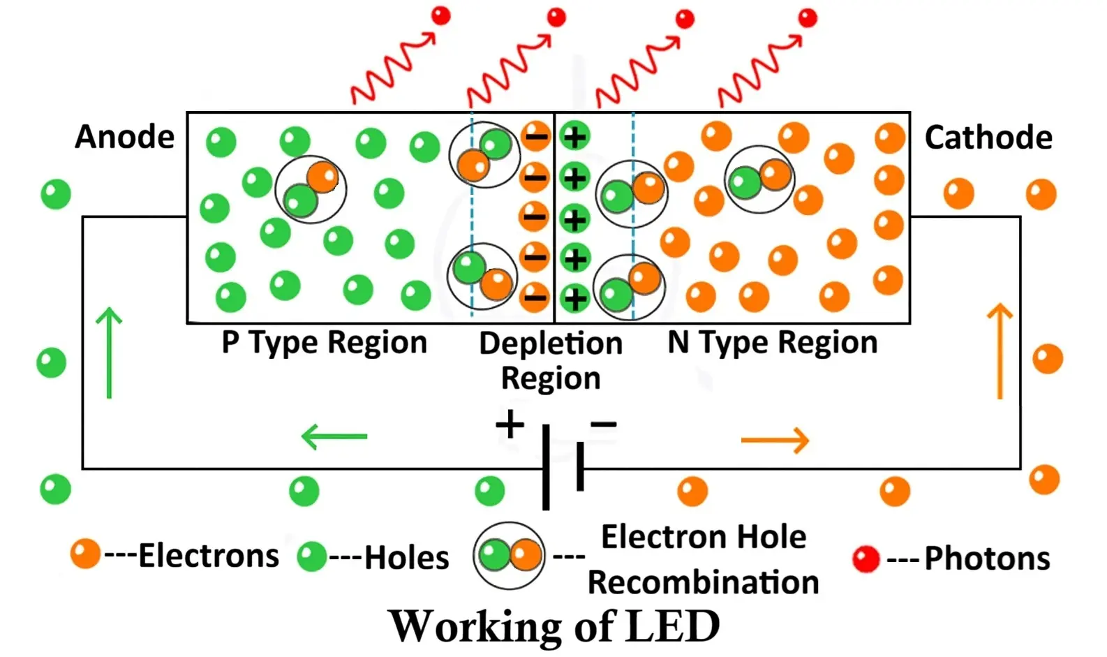
Forward Bias Operation of LED
- The n-type region has electrons as majority charge carriers.
- The p-type region has holes as majority charge carriers.
- The n-layer is generally more heavily doped than the p-layer to facilitate electron movement.
When a voltage is applied in the forward direction, the external electric field pushes:
- Electrons from the n-side toward the junction, and
- Holes from the p-side toward the junction.
This action reduces the width of the depletion region (the barrier that normally prevents current flow), allowing charge carriers to move freely across the junction.
As electrons cross the depletion zone, they recombine with holes in the active region. During this recombination process, electrons transition from a higher energy state (in the conduction band) to a lower energy state (in the valence band). The energy difference between these two bands is released in the form of photons — the fundamental particles of light.
The rate of recombination increases as the current rises, resulting in greater light intensity. This emission of light through electrical excitation is called electroluminescence, which forms the foundation of LED operation.
Electroluminescence and Energy Conversion
The ability of certain semiconductors to convert electrical energy into light energy is known as electroluminescence.
Only specific materials such as Gallium Arsenide (GaAs), Gallium Phosphide (GaP), and Gallium Arsenide Phosphide (GaAsP) exhibit this property.
In contrast, materials like silicon (Si) and germanium (Ge) cannot emit visible light efficiently; they primarily release the energy as heat rather than photons. The reason behind this lies in the energy band structure of the material.
Light Emission and Energy Band Theory
To understand why LEDs emit light, we must refer to the energy band theory of solids.
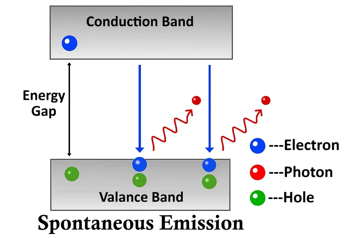
In a semiconductor crystal, electrons can occupy specific energy bands:
- The valence band — where electrons are bound to atoms (low energy state).
- The conduction band — where electrons are free to move (high energy state).
The gap between these two bands is known as the energy gap (Eg).
When an electron drops from the conduction band to the valence band, it releases energy equal to this gap:
E = hν
Where:
- (E) = energy released,
- (h) = Planck’s constant,
- (ν) = frequency of the emitted photon.
If the semiconductor material has a direct band gap, the energy is released as light (photon emission).
If it has an indirect band gap, the energy is released primarily as heat (phonon emission).
1. Direct Band Gap Semiconductors
In direct band gap materials, the conduction band and valence band align vertically in the energy–momentum (E–k) diagram. This means that electrons can fall directly from the conduction band to the valence band without changing their momentum.
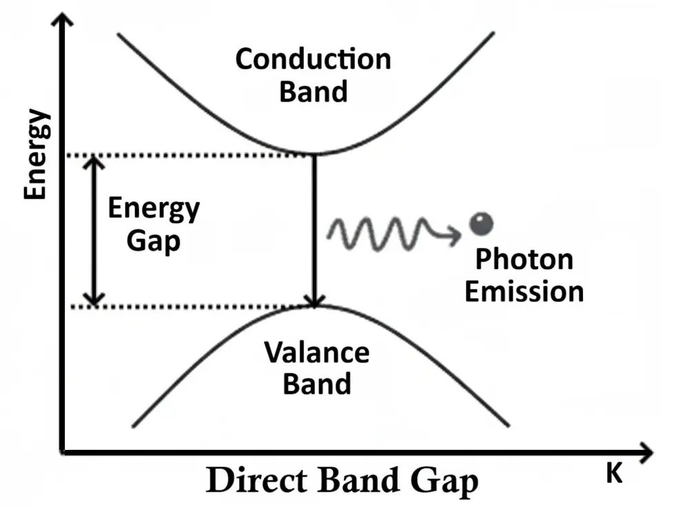
During this transition, the released energy appears as visible or infrared light, depending on the size of the energy gap. The larger the band gap, the higher the energy (and shorter the wavelength) of the emitted light.
Such materials are ideal for LED construction.
Examples of Direct Band Gap Semiconductors:
- Gallium Arsenide (GaAs) – emits infrared light
- Gallium Arsenide Phosphide (GaAsP) – emits red or yellow light
- Aluminium Gallium Arsenide (AlGaAs) – used for high-efficiency red LEDs
- Indium Gallium Nitride (InGaN) – produces blue and green LEDs
- Zinc Selenide (ZnSe) – emits blue light
Each material’s band gap determines the color (wavelength) of light produced:
λ = hc/Eg
where λ is wavelength, h is Planck’s constant, c is the speed of light, and Eg is the band gap energy.
2. Indirect Band Gap Semiconductors
In indirect band gap materials, such as silicon and germanium, the conduction and valence bands are misaligned on the E–k diagram — they occur at different momenta (k-values).
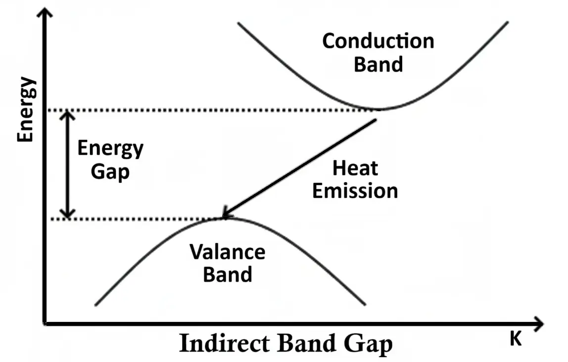
When an electron falls from the conduction band to the valence band, it must also change its momentum, which requires the involvement of a phonon (a quantum of heat energy). As a result, the energy is released as heat instead of light.
This is why silicon and germanium diodes cannot emit visible light and are used for switching and rectification purposes, not illumination.
Colors of Light Emitting Diode (LED)
LEDs are available in a wide range of colors — from infrared and ultraviolet to visible shades like red, green, blue, and white. But what exactly determines the color of the light an LED emits?
The color of light produced by an LED depends primarily on the semiconductor material used and its energy band gap (Eg). Each material emits light of a specific wavelength when electrons and holes recombine in the active region. Because each wavelength corresponds to a distinct color in the visible spectrum, the chemical composition of the LED material ultimately decides its color.
In simple terms, different semiconductor compounds produce different colors of light due to variations in their band gap energies. A larger band gap produces light of a shorter wavelength (higher energy, such as blue or violet), while a smaller band gap results in longer wavelength light (lower energy, such as red or infrared).
Relation Between Band Gap and Color
Each LED color corresponds to a specific wavelength (λ) of light, and the energy of that light can be expressed as:
E = hc/λ
Where:
- E = energy of emitted photon (related to the band gap),
- h = Planck’s constant,
- c = speed of light,
- λ = wavelength of emitted light.
Thus, materials with larger energy gaps emit photons of higher frequency and shorter wavelength, producing colors toward the violet and blue region of the spectrum. Conversely, materials with smaller energy gaps emit red or infrared light.
Table of LED Colors, Materials, and Forward Voltage
The table below summarizes the key parameters — color, wavelength, forward voltage, and semiconductor materials used for LEDs of various colors.
| Color | Wavelength (nm) | Forward Voltage (V) | Semiconductor Material(s) |
|---|---|---|---|
| White | 395 – 530 | 3.0 – 5.0 | Gallium Indium Nitride (GaInN), Zinc Selenide (ZnSe) |
| Ultraviolet (UV) | < 400 | 3.1 – 4.4 | Aluminum Nitride (AlN), Aluminum Gallium Nitride (AlGaN), Aluminum Gallium Indium Nitride (AlGaInN) |
| Violet | 400 – 450 | 2.8 – 4.0 | Indium Gallium Nitride (InGaN) |
| Blue | 450 – 500 | 2.5 – 3.7 | Indium Gallium Nitride (InGaN), Silicon Carbide (SiC) |
| Green | 500 – 570 | 1.9 – 4.0 | Gallium Phosphide (GaP), Aluminum Gallium Indium Phosphide (AlGaInP), Aluminum Gallium Phosphide (AlGaP) |
| Yellow | 570 – 590 | 2.1 – 2.2 | Gallium Arsenide Phosphide (GaAsP), AlGaInP, GaP |
| Orange | 590 – 610 | 2.0 – 2.1 | Gallium Arsenide Phosphide (GaAsP), AlGaInP, GaP |
| Red | 610 – 760 | 1.6 – 2.0 | Aluminum Gallium Arsenide (AlGaAs), GaAsP, AlGaInP, GaP |
| Infrared (IR) | > 760 | < 1.9 | Gallium Arsenide (GaAs), Aluminum Gallium Arsenide (AlGaAs) |
Each of these materials are carefully selected based on the desired wavelength and brightness for a particular application. For instance, red LEDs are commonly used for power indicators, blue and white LEDs for illumination, and infrared LEDs for remote controls and sensors.
White Light LEDs
Interestingly, there is no single semiconductor that naturally emits white light.
White LEDs are typically created by:
- Combining red, green, and blue (RGB) LEDs in one package to produce white light by additive color mixing.
- Using a blue or ultraviolet LED coated with a phosphor material that converts part of the light into other colors — the blend of these results in white light.
This is how modern white LED bulbs achieve a bright, natural-looking light output.
Biasing of LED
Like an ordinary PN junction diode, an LED functions only when it is forward biased. In this condition, the anode (+) is connected to the positive terminal of the power source, and the cathode (−) is connected to the negative terminal.
When the applied voltage exceeds the forward voltage (Vf) of the LED:
- The depletion region narrows, allowing current to flow.
- Electrons recombine with holes in the active region.
- Light is emitted as a result of electroluminescence.
Current Limiting and Safe Operation
However, LEDs are very sensitive to current and voltage. Once the LED begins conducting, the current rises sharply with only a small increase in voltage. Without proper current control, this can cause permanent damage to the LED junction.
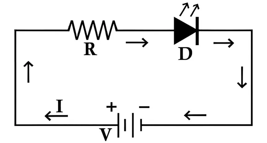
To prevent this, a current-limiting resistor is connected in series with the LED.
Current-limiting resistor calculation:
R = (VS - VF)/I
Where:
- R = resistor value,
- VS = supply voltage,
- VF = LED forward voltage,
- I = desired forward current (typically 10–30 mA for standard LEDs).
Example:
If the supply voltage is 5V, the LED forward voltage is 2V, and the desired current is 20mA:
R = (5 - 2)/0.02 = 150Ω
Operating Limits
- Forward Voltage: Typically ranges from 1.6V (red) to 4.0V (blue/white) depending on color.
- Forward Current: Usually between 10mA to 30mA for standard LEDs.
- Reverse Voltage: Must always be avoided — LEDs are not designed to handle reverse bias beyond a few volts.
If the supply voltage exceeds the LED’s rated forward voltage, the excessive current can overheat and destroy the junction. Therefore, both voltage and current must always be limited within the manufacturer’s specifications.
Output Characteristics of LED
The output characteristics of an LED describe how the light output (optical power or intensity) varies with the forward current (IF) flowing through the diode. These characteristics are important because they define how efficiently the LED converts electrical energy into visible light.
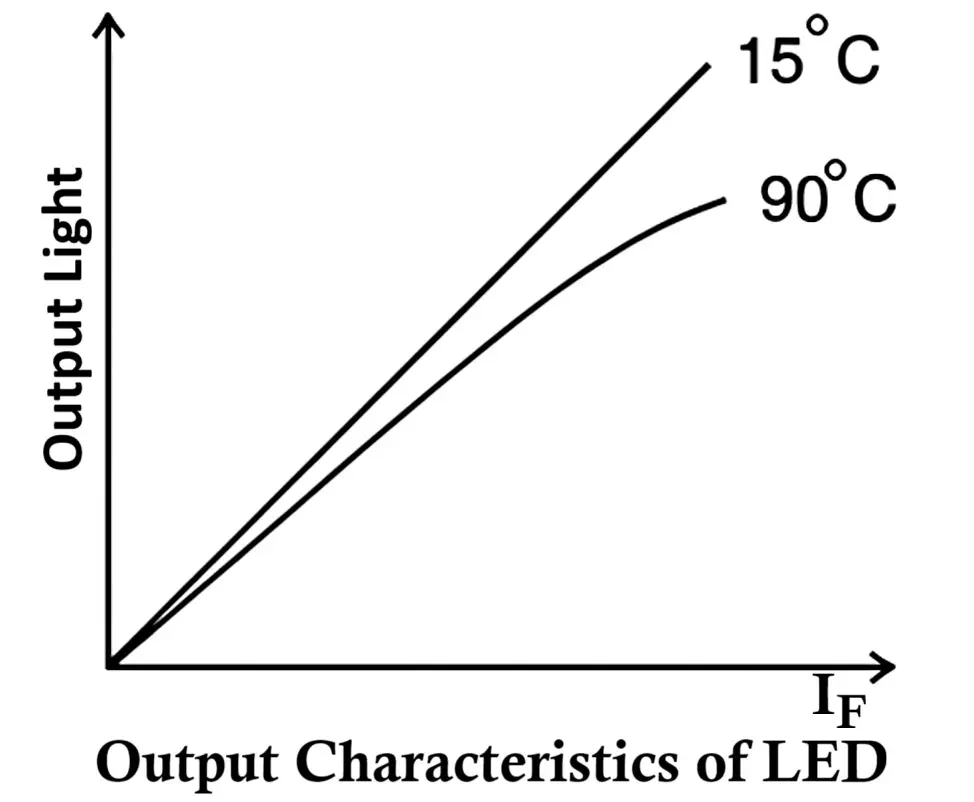
In a typical output characteristic curve:
- The horizontal axis (X-axis) represents the forward current (IF), and
- The vertical axis (Y-axis) represents the light intensity (or radiant power) emitted by the LED.
Relationship Between Light Intensity and Forward Current
The light intensity of an LED is directly proportional to the forward current. As the forward current increases, more electrons and holes recombine in the active region, resulting in a greater number of photons being emitted. Mathematically, this relationship can be expressed as:
Popt ∝ IF
Where:
- Popt = Optical power (light intensity)
- IF = Forward current through the LED
However, this linear relationship holds true only up to a certain limit. If the current is increased excessively beyond the LED’s rated value, the junction temperature rises, reducing efficiency and possibly causing permanent damage to the LED.
Effect of Temperature on Light Output
Temperature has a significant impact on LED performance.
As the junction temperature increases, the light output decreases — even if the forward current remains constant. This is due to a reduction in the recombination efficiency and a shift in the emission wavelength.
In short:
- Higher temperature → Lower light intensity
- Lower temperature → Higher light intensity
Therefore, maintaining proper thermal management through heat sinks or current regulation circuits is crucial for high-power LEDs to ensure long-term stability and consistent brightness.
This illustrates the importance of both current control and thermal regulation in LED design and applications.
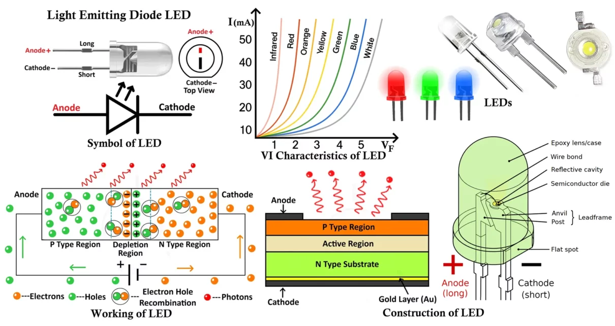
VI Characteristics of LED
The VI (Voltage Current) characteristic of an LED defines the relationship between the applied voltage across the LED and the current flowing through it.
When the LED is forward biased, it behaves like a normal PN junction diode. Initially, for small voltages, almost no current flows because the depletion region acts as a barrier. As the applied voltage increases and reaches a specific threshold (known as the knee voltage or forward voltage (VF)), the LED begins to conduct current rapidly, and light emission starts.
The knee voltage for LEDs is higher than that of ordinary silicon diodes (which is around 0.7V). This is because LED materials such as GaAs, GaP, or InGaN have larger band gaps. Depending on the LED color (and hence material), the forward voltage typically ranges from 1.6V to 4.0V.
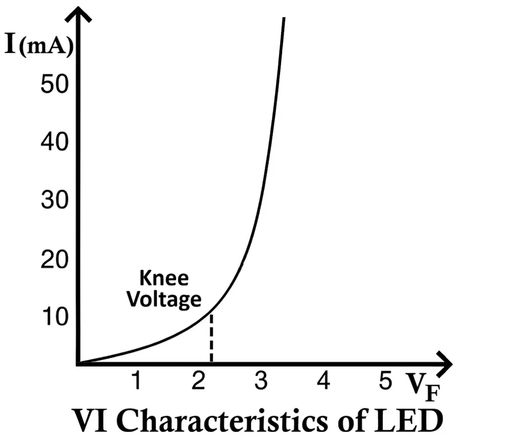
Key Observations from the VI Characteristics
- No Conduction Below Threshold:
At voltages below the knee voltage, the LED does not conduct and hence does not emit light. - Exponential Current Rise After Threshold:
Once the forward voltage exceeds the threshold, the current rises exponentially with voltage, similar to a standard diode. The light intensity also increases proportionally with this current. - Different Colors → Different Knee Voltages:
Each LED color corresponds to a different semiconductor material and band gap, resulting in different forward voltage values.For example:- Red LED: ~1.8 – 2.2V
- Green LED: ~2.0 – 3.2V
- Blue/White LED: ~3.0 – 3.6V
- Infrared LED: ~1.2 – 1.9V
- Higher Band Gap → Higher Forward Voltage:
As the wavelength of emitted light decreases (from infrared to ultraviolet), the band gap energy increases, and so does the forward voltage required for operation.
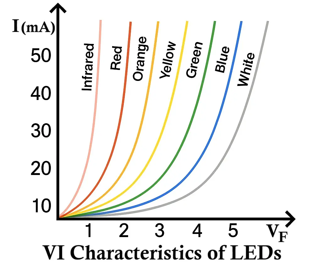
Relation Between Wavelength and Forward Voltage
The order of LED color from longest to shortest wavelength (and hence from lowest to highest forward voltage) is:
Infrared → Red → Orange → Yellow → Green → Blue → Violet → Ultraviolet
This means that:
- Infrared LEDs (long wavelength) have lowest forward voltage,
- Blue and UV LEDs (short wavelength) have highest forward voltage.
Types of Light Emitting Diode (LED)
There Different types of LEDs based on color, packaging, application and circuit design, let’s explore all these types one by one.
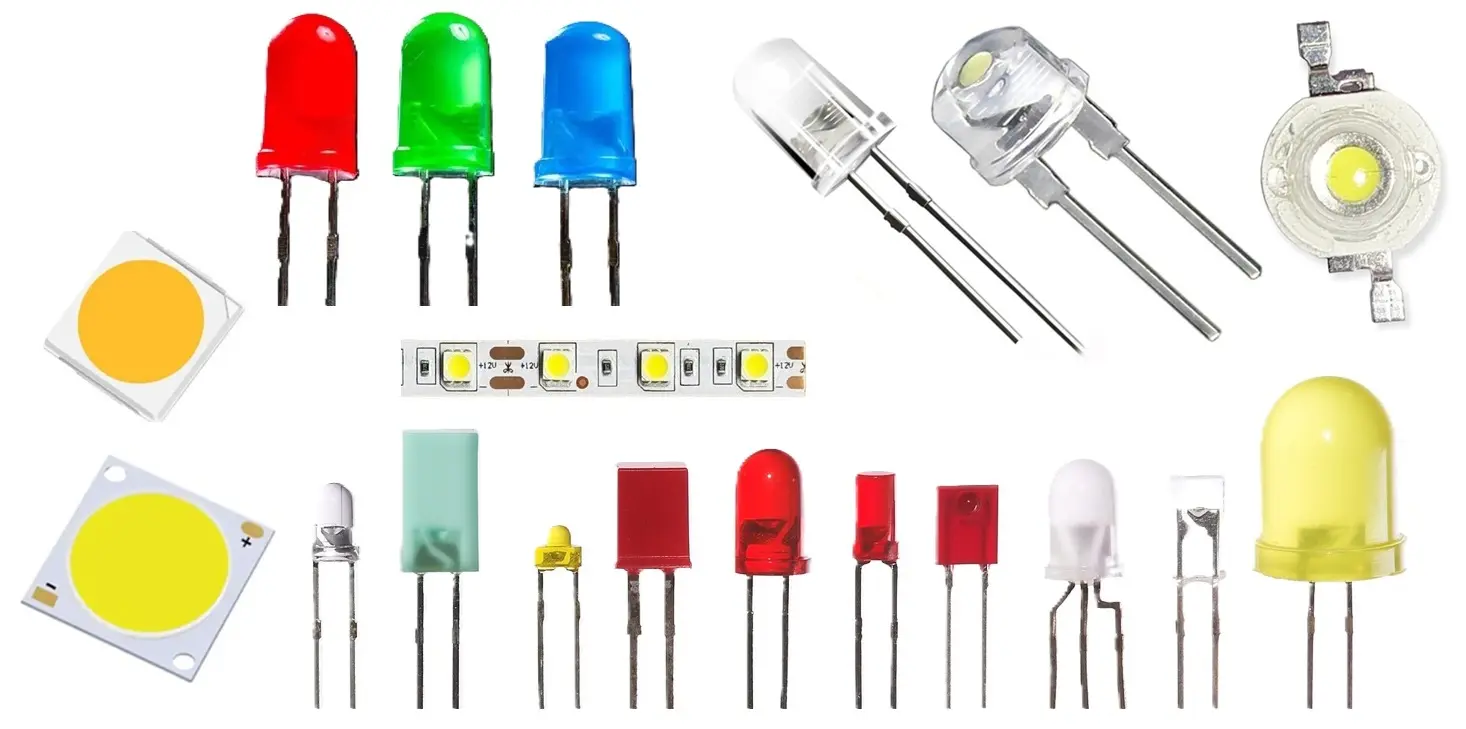
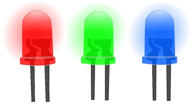
- By Color: IR, Red, Green, Blue, White, UV, RGB
- By Package: DIP, SMD, COB, CSP, Flip-Chip, Micro, Mini
- By Function: Indicator, Display, Lighting, Automotive, Smart
- By Circuit: Single, Bi-color, RGB, Addressable, Flashing
- Specialty: OLED, QLED, UV-C, Grow, Laser, Filament
1. By Color / Wavelength
- Infrared (IR) LED – Emits invisible light (700–1100 nm); used in remotes, sensors, and night vision.
- Red LED – Early LED color; used in indicators, alarms, displays, and brake lights.
- Orange / Amber LED – Common in automotive signals, signs, and warning lights.
- Yellow LED – Used for caution indicators and decorative applications.
- Green LED – For displays, power indicators, and signal systems.
- Blue LED – Enables white light generation (with phosphor); used in modern lighting and electronics.
- White LED – Usually a blue LED coated with yellow phosphor; for general lighting and flashlights.
- Ultraviolet (UV) LED – For disinfection, curing, and forensic applications.
- RGB LED – Combines Red, Green, and Blue chips to create millions of colors.
- RGBW / RGBA LED – Adds a white or amber chip for richer, more natural colors.
2. By Package / Construction
- DIP (Dual Inline Package) LED – Classic round “bulb” style (3mm, 5mm, 8mm, 10mm).
- SMD (Surface-Mount Device) LED – Compact and flat; popular in strip lights and displays.
- Common SMD sizes: 3528, 2835, 5050, 5630, 3014, 3030.
- COB (Chip-on-Board) LED – Multiple chips on a substrate; high brightness and uniform light.
- High-Power LED – Handles high current (1W, 3W, 5W+); needs heat sinks.
- Micro LED – Microscopic LEDs for next-gen TVs, AR/VR, and smart displays.
- Mini LED – Smaller than standard SMD; used in backlights for high-contrast displays.
- Flip-Chip LED – Mounted upside down; better heat and light efficiency.
- CSP (Chip Scale Package) LED – Ultra-compact LEDs with minimal packaging; used in dense arrays.
3. By Function / Application
- Indicator LED – Status lights on electronics (power, standby, signal).
- Display LED – Used in numeric displays, dot matrices, and signage.
- Backlight LED – Provides illumination behind LCD panels (TVs, monitors, phones).
- Lighting / Illumination LED – Used in bulbs, streetlights, and home lighting.
- Flash LED – High-intensity bursts for cameras and smartphones.
- Signage / Advertising LED – For billboards, message boards, and outdoor displays.
- Automotive LED – For headlights, taillights, DRLs, and dashboards.
- Smart / Digital LED – Controlled via Wi-Fi, Bluetooth, or ICs (e.g., WS2812B, SK6812).
- UV-C LED – Emits germicidal UV light (200–280 nm) for sterilization.
- Horticulture / Grow LED – Red and blue spectrum for plant growth.
4. By Electrical / Circuit Configuration
- Single-Color LED – Emits one fixed color.
- Bi-Color LED – Two LEDs in one package; changes color with polarity.
- Tri-Color (RGB) LED – Three LEDs (red, green, blue) in one package.
- Addressable / Programmable LED – Each LED has its own control chip (e.g., WS2812, SK6812).
- Flashing LED – Built-in oscillator makes it blink automatically.
- Photo-LED / Light-Sensing LED – Can act as a light detector in some circuits.
5. Specialty & Advanced LEDs
- OLED (Organic LED) – Flexible, thin, and used in phone and TV screens.
- QLED (Quantum Dot LED) – Uses nanocrystals for vivid color and brightness (Samsung TVs).
- Laser Diode – Similar to LEDs but emits coherent light; used in optical drives and LIDAR.
- UV-C LED – Specialized UV emitters for disinfection and purification.
- COB Filament LED – Thin LED strips that mimic incandescent filaments.
- Grow Light LED – Tailored light spectrum for horticulture and indoor farming.
- IR Proximity LED – Used in motion detectors, gesture sensors, and phones.
- Optical / Photo-IR LED – Used in encoders and optical communication systems.
Advantages and Disadvantages of LEDs
Like any other electronic component, LEDs have both strengths and limitations. Let’s explore the advantages and disadvantages of LEDs in detail.
Advantages of LED
- Wide Operating Temperature Range with Stability:
LEDs operate reliably between 0°C and 70°C, with consistent brightness and efficiency across varying conditions without flickering or dimming. - Mechanical Strength and Durability:
LEDs are solid-state devices with no fragile filaments or glass enclosures, making them highly resistant to vibration, shock, and mechanical stress. - Long Lifespan:
A well-designed LED can last between 50,000 and 100,000 hours, significantly longer than incandescent or fluorescent lamps. - Low Voltage and Power Consumption:
LEDs operate on low DC voltages (1.8V – 4V) and current (10–30mA), ideal for battery-powered and energy-efficient applications. - Compact Size and Design Flexibility:
LEDs can be manufactured in any shape or size, enabling their use in compact electronic devices, displays, and high-density arrays for alphanumeric and graphical displays. - Electrical Isolation via Optocouplers:
LEDs are part of optoisolators, which transmits signal optically between circuits while maintaining electrical isolation, enhancing safety and reliability. - Cost-Effective and Reliable:
LEDs are economical in the long run due to their low energy consumption, minimal maintenance, and extended lifespan. - Fast Switching Speed:
LEDs switch on and off within nanoseconds (≈1ns), making them ideal for high-speed communication and dynamic lighting applications. - Variety of Colors:
LEDs can emit multiple colors (red, green, yellow, blue, orange, white, etc.) depending on the semiconductor material used. - Brightness Control:
The intensity or brightness of an LED can be easily adjusted by varying the forward current. - Energy Efficiency:
LEDs are more efficient than incandescent and CFL bulbs. - Environmentally Friendly:
LEDs do not contain mercury, halogens, or toxic gases.
Disadvantages of LED
- Polarity Sensitive:
Since LEDs are diodes, they are unidirectional and must be connected in forward bias. Incorrect polarity or reverse voltage can damage the LED permanently. - Not Suitable for Reverse Bias Operation:
LEDs can tolerate only a small reverse voltage (typically < 5V). A higher reverse bias can destroy the junction. - Higher Cost for Large Displays:
Though small LEDs are inexpensive, large LED panels or high-power LEDs are relatively costlier compared to LCD alternatives. - Higher Forward Voltage:
LEDs require higher forward voltages (1.6V–4V) than conventional silicon diodes due to their active light-emitting region. - Current and Voltage Sensitivity:
LEDs are extremely sensitive to current spikes and overvoltage, which can lead to thermal runaway and junction failure. Proper current limiting is mandatory. - Overheating Issues:
High-power LEDs can generate heat during operation. Without adequate heat sinking or cooling, this can reduce their lifespan. - Efficiency Droop:
As current increases beyond optimal levels, LED efficiency decreases — a phenomenon known as efficiency droop. - Color Shift Over Time:
Prolonged operation or excessive heat can cause the color of emitted light to shift, affecting brightness and consistency. - Initial Cost:
Although long-term savings are significant, the initial purchase cost of LEDs is higher than that of incandescent or fluorescent lamps. - Limited Backlight Efficiency for Displays:
Compared to LCDs, standard LEDs are not as energy-efficient for large display panels, especially in full white or high-brightness modes.
Applications of LED
Due to their versatility, efficiency, and compactness, LEDs are used in virtually every field of electronics and illumination. Below are the major application areas:
- Illumination and Lighting
- Used for domestic, industrial, and street lighting due to their high luminous efficiency and low power consumption.
- Integrated into flashlights, emergency lamps, floodlights, and torchlights.
- Indicators and Displays
- Serve as status indicators in electronic devices, showing power, operation, or fault status.
- Used in digital clocks, calculators, meters, and instrumentation panels.
- Employed in seven-segment displays and dot-matrix modules for text or number representation.
- Traffic and Automotive Applications
- Used in traffic signals, vehicle brake lights, turn indicators, and dashboard illumination due to fast response and durability.
- Communication and Control Systems
- Infrared LEDs are widely used in remote controls for TVs, air conditioners, and cameras.
- Used in optical communication systems such as fiber optics and IR transmitters.
- Security and Sensing
- Used in burglar alarm systems and motion detectors where an infrared LED and photodiode pair detects movement or interruption of a light beam.
- Employed in optocouplers for electrical isolation between control and power circuits.
- Medical and Scientific Equipment
- Used in medical diagnostic devices, surgical lighting, and biophotonic systems.
- UV LEDs are used for sterilization and disinfection in laboratories and hospitals.
- Decorative and Display Applications
- Found in festive decorations, stage lighting, and architectural illumination.
- Integrated into toys, art installations, and commercial signage due to their vibrant colors and programmable control.
- Photography and Imaging
- Used in camera flash units, studio lighting, and ring lights for photography and videography.
- Data Transmission and Optical Communication
- Laser LEDs that emit monochromatic light are used in fiber optic communication, enabling high-speed data transfer over long distances.
- Specialized and Industrial Uses
- Infrared LEDs for machine vision systems, barcode scanners, and biometric sensors.
- UV LEDs for curing adhesives, forensic detection, and material analysis.
Conclusion
The Light Emitting Diode (LED) is a groundbreaking innovation that has transformed modern electronics and lighting. Based on the principle of electroluminescence, LEDs efficiently convert electrical energy into light, offering unmatched efficiency, longevity, and versatility.
From homes and vehicles to communication and medical systems, LEDs are vital to countless applications. Despite minor drawbacks like heat sensitivity and higher initial cost, their energy savings, durability, and eco-friendliness make them the leading choice for sustainable illumination.
In essence, the LED is more than a light source — it’s the bright future of smart and energy-efficient technology.
Laser Diode – Symbol, Construction, Working, Types and Applications
Types of Diodes with Symbol, Definition, Working and Applications
VI Characteristics of Zener Diode, Working and its Applications
Light Dependent Resistor (LDR) / Photoresistor Circuit Diagram & Working
