Temperature monitoring is a fundamental requirement in modern electronic systems, ranging from consumer appliances and industrial equipment to power electronics and laboratory instruments. An LED temperature display circuit using LM3915 and a thermistor offers a simple, reliable, and visually intuitive way to indicate temperature variations without the complexity of microcontrollers or digital displays.
This circuit converts temperature changes sensed by a thermistor into a corresponding LED bar or dot display. As temperature rises or falls, LEDs illuminate progressively, providing an immediate visual indication of the temperature range. Because the LM3915 operates in logarithmic steps and requires minimal external components, the overall design remains cost-effective and robust.
Need for Temperature Display Circuits
Temperature display circuits are widely used because:
- Excessive temperature can damage electronic components
- Many systems require visual temperature indication rather than numeric values
- LED displays are easy to read in dark or harsh environments
- Analog circuits are preferred in noise-prone industrial conditions
Typical applications include:
- Heat sinks and power amplifiers
- Battery packs and chargers
- Transformers and SMPS units
- Industrial panels and control cabinets
Overview of LM3915 IC
The LM3915 is a monolithic integrated circuit designed to drive LED displays directly from an analog input signal. It compares the input voltage against internally generated reference levels and turns on LEDs accordingly.
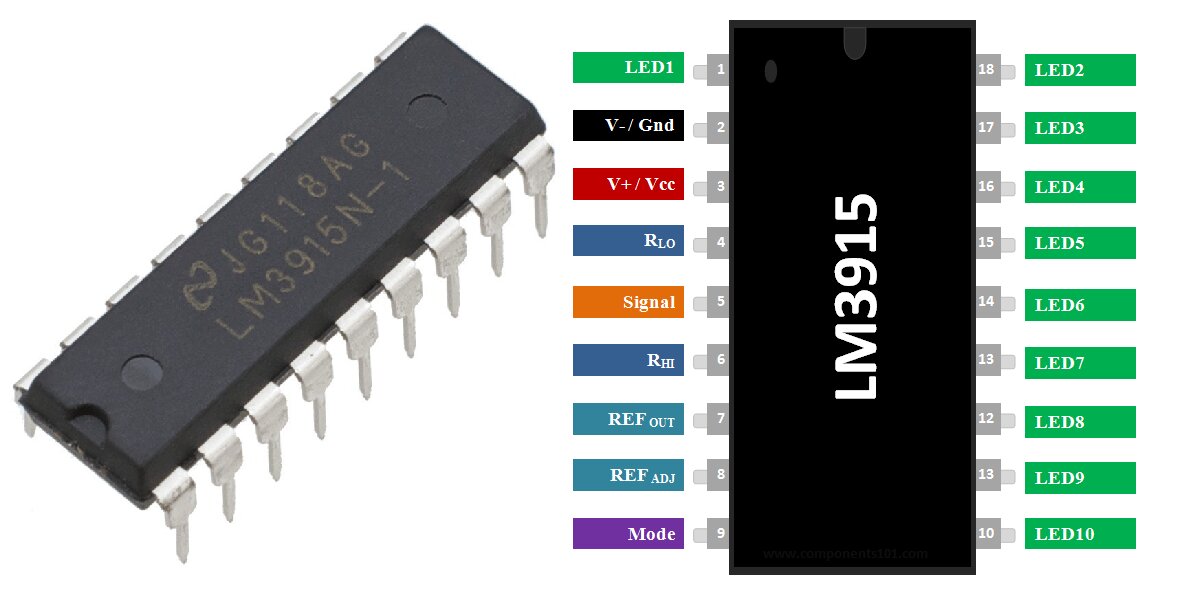
Key Features of LM3915
- Drives up to 10 LEDs directly
- Operates in dot mode or bar mode
- Logarithmic scale (3 dB per step)
- No need for external current-limiting resistors for LEDs
- Wide supply voltage range (3 V to 25 V)
Although the LM3914 (linear scale) is commonly used for voltmeters, the LM3915’s logarithmic response provides better visual resolution for wide-ranging signals such as temperature variations.
Related Articles:
- LM3915 Based LED VU Meter Circuit Diagram and Working
- LM3915 LED Battery Voltage Level Indicator Circuit Diagram
Thermistor as Temperature Sensor
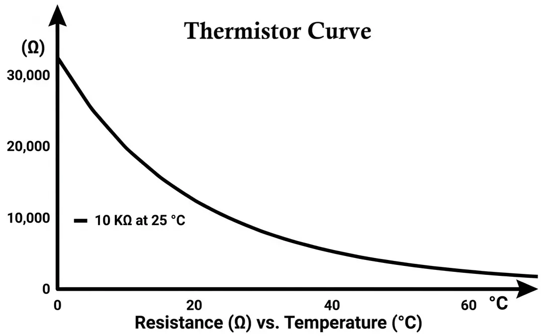
A thermistor is a temperature-dependent resistor. In this circuit, an NTC (Negative Temperature Coefficient) thermistor is used.
Characteristics of NTC Thermistor
- Resistance decreases as temperature increases
- High sensitivity compared to RTDs
- Small size and low cost
- Non-linear resistance–temperature relationship
The thermistor is typically connected in a voltage divider configuration, producing a temperature-dependent voltage that is fed into the LM3915 input.
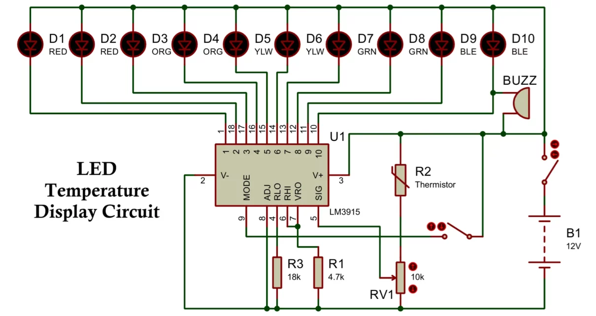
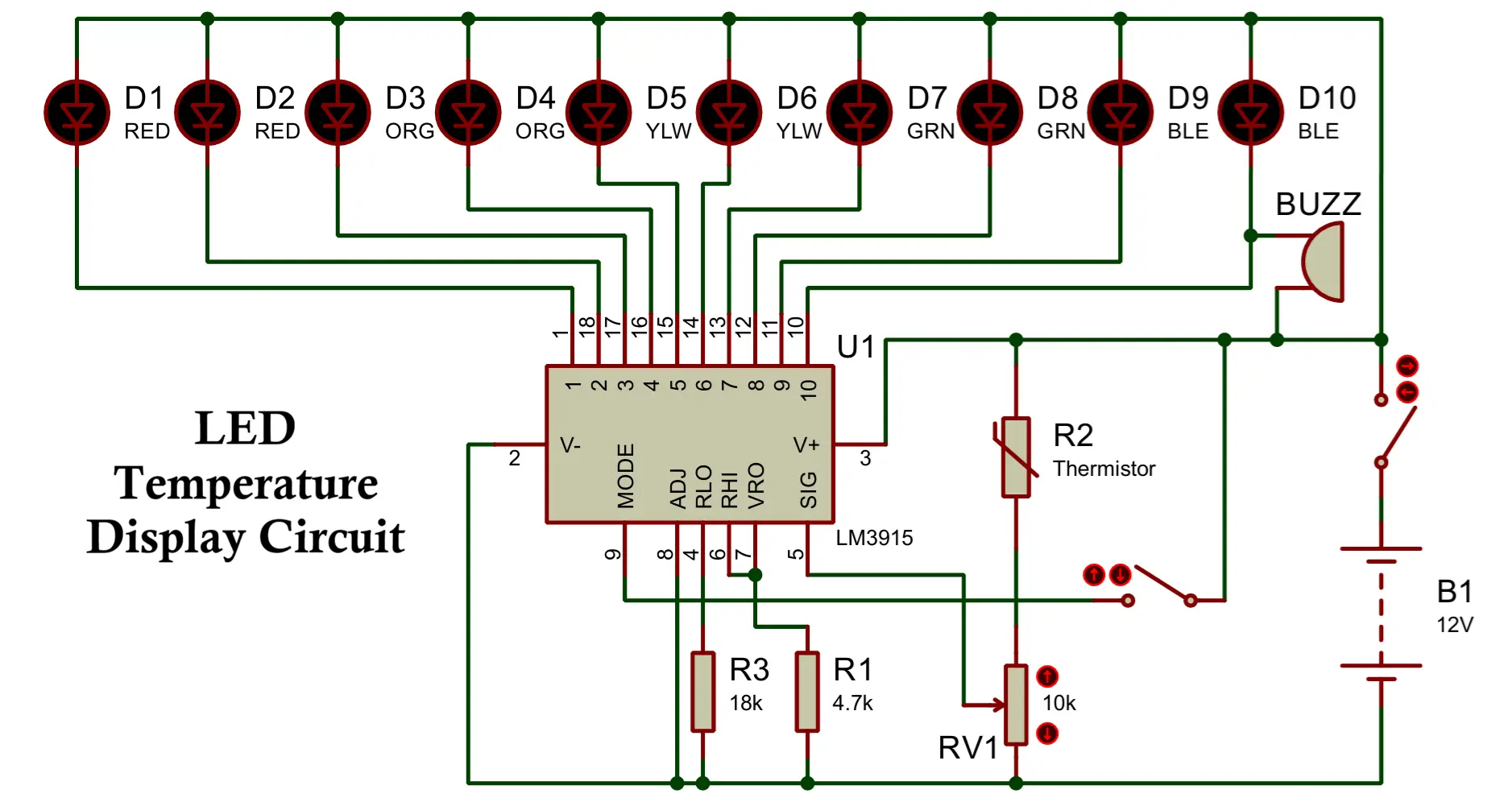
LED Temperature Display Circuit Diagram
Main Components
- LM3915 IC
- NTC thermistor (10 kΩ at 25°C commonly used)
- Fixed resistors and preset potentiometer
- 10 LEDs (bar or dot indication)
- DC power supply (9 V to 12 V recommended)
Working Principle of the Circuit
The operation of the LED temperature display circuit can be understood in the following stages:
- Temperature Sensing: The thermistor senses ambient temperature. As temperature rises, its resistance decreases.
- Voltage Conversion: The thermistor, in combination with a fixed resistor, forms a voltage divider. The output voltage varies with temperature.
- Signal Conditioning: A preset potentiometer is used to calibrate the voltage range so that it matches the LM3915 input span.
- Voltage Comparison: The LM3915 compares the input voltage with its internal reference levels.
- LED Indication: Based on the input voltage:
- Lower temperature → fewer LEDs glow
- Higher temperature → more LEDs glow
- In bar mode, all LEDs up to the measured level remain ON.
- In dot mode, only one LED glows at a time, reducing power consumption.
Calibration of Temperature Range
Calibration is critical to ensure meaningful temperature indication.
Typical Calibration Steps
- Set the thermistor at a known temperature (e.g., room temperature)
- Adjust the preset so the first LED just turns ON
- Increase temperature gradually (using warm air or a controlled source)
- Adjust upper reference so the last LED turns ON at maximum desired temperature like LED 1 → 20°C, LED 5 → 40°C, LED 10 → 80°C.
- Also, you can integrate alarm indication.
LED Display Modes
Dot Mode
- Only one LED ON at a time
- Lower power consumption
- Suitable for battery-powered systems
Bar Mode
- All LEDs up to the level remain ON
- Better visual representation of temperature trend
- Suitable for panel-mounted indicators
Mode selection is achieved by proper connection of the LM3915 mode-select pin.
Advantages of LED Temperature Display
- Simple and compact circuit design
- No microcontroller or programming required
- High reliability due to analog operation
- Visual temperature indication without numeric display
- Wide operating voltage range
Disadvantages of LED Temperature Display
- Temperature scale is approximate due to thermistor non-linearity
- Not suitable for precision temperature measurement
- Limited to 10-step resolution
- Requires manual calibration
Applications
- Heat sink temperature monitoring
- Power amplifier thermal indication
- Battery pack temperature display
- Transformer and SMPS thermal monitoring
- Educational and laboratory demonstration circuits
Practical Design Tips
- Use matched LEDs for uniform brightness
- Place thermistor close to the heat source for accurate sensing
- Add a small capacitor at the input to reduce noise
- Prefer dot mode for low-power designs
- Use a regulated power supply for stable operation
Conclusion
The LED temperature display circuit using LM3915 and thermistor is a classic and effective solution for real-time temperature indication. Its simplicity, low cost, and visual clarity make it ideal for both hobbyist projects and industrial monitoring applications. While it does not provide numerical accuracy, it excels as a quick-reference thermal indicator where reliability and ease of implementation are more important than precision.
If required, this design can later be enhanced by replacing the thermistor with linear temperature sensors or LM35 temperature sensor.
IOT Based Air Quality Monitoring System with ESP32 & BME680 Sensor
3 Simple IR Proximity Sensor Circuits with Working & Applications
