Discover the fundamental differences between BJT and JFET. Learn about their structures, control mechanisms, advantages, and ideal applications in electronic circuits.
Transistors are the fundamental building blocks of modern electronic devices, acting as switches or amplifiers in circuits. There are various types of transistors like BJT, FET, JFET, MOSFET and IGBT. Let’s see a detailed comparison of Bipolar Junction Transistors (BJTs) and Junction Field Effect Transistors (JFETs):
What is a BJT?
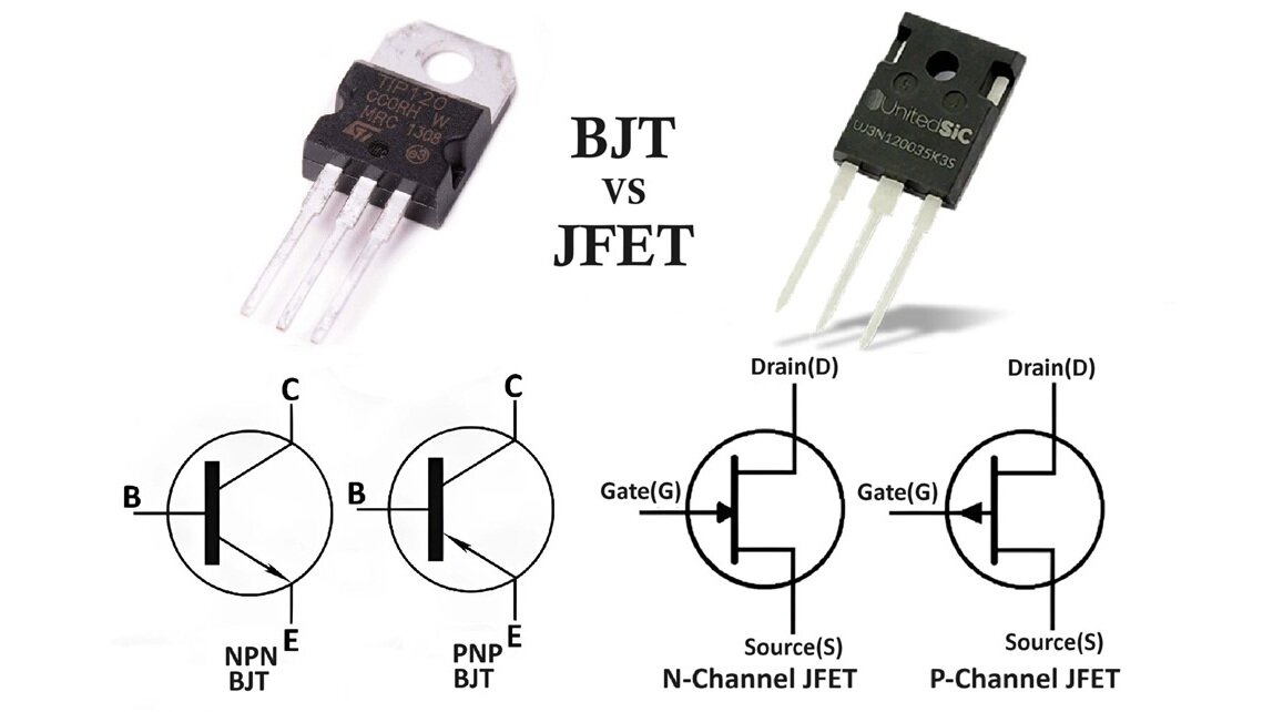
A Bipolar Junction Transistor (BJT) is a type of transistor that relies on the movement of both electrons and holes for its operation. It consists of three layers of semiconductor material, forming two p-n junctions. The three layers are known as the emitter, base, and collector. BJTs come in two polarities: NPN and PNP.

- NPN Transistor: Consists of a layer of P-doped semiconductor between two N-doped layers.
- PNP Transistor: Consists of a layer of N-doped semiconductor between two P-doped layers.
In a BJT, current flows between the collector and the emitter terminals and is controlled by the current applied to the base terminal. This means that BJTs are current-controlled devices.
What is a JFET?
A Junction Field Effect Transistor (JFET) is a type of transistor that relies solely on the movement of majority carriers (either electrons or holes) for its operation. It consists of a channel of semiconductor material (N-type or P-type) with two terminals at each end, known as the source and drain, and a gate terminal that controls the flow of carriers through the channel.

- N-channel JFET: Has an N-type channel with a P-type gate.
- P-channel JFET: Has a P-type channel with an N-type gate.
In a JFET, the current flows between the source and drain terminals and is controlled by the voltage applied to the gate terminal. This makes JFETs voltage-controlled devices.
Key Differences Between BJT and JFET:
Control Mechanism:
BJT: Current-controlled device. The base current controls the collector-emitter current.
JFET: Voltage-controlled device. The gate-source voltage controls the drain-source current.
Input Impedance:
BJT: Low input impedance, typically in the range of a few kilo-ohms. This can load the preceding stage in a circuit.
JFET: High input impedance, often in the range of mega-ohms to giga-ohms. This results in minimal loading of the preceding stage.
Output Characteristics:
BJT: Output current is almost independent of the collector-emitter voltage in the active region, making it suitable for amplification.
JFET: Output current varies with drain-source voltage but becomes constant in the saturation region, similar to a constant current source.
Power Consumption:
BJT: Higher power consumption due to the need for base current.
JFET: Lower power consumption as it requires almost no gate current.
Noise Performance:
BJT: Generally higher noise levels due to the recombination of electrons and holes.
JFET: Lower noise levels, making them ideal for low-noise applications like audio and radio frequency amplifiers.
Thermal Stability:
BJT: Less thermally stable due to the reliance on both electrons and holes.
JFET: More thermally stable since only majority carriers are involved.
Frequency Response:
BJT: Better suited for high-frequency applications due to faster switching times.
JFET: Generally limited to lower frequency applications compared to BJTs.
Advantages and Disadvantages of BJT:
Here’s an in-depth look at what makes BJTs beneficial and where they might fall short.
Advantages of BJT:
High Gain:
BJTs offer high current and voltage gain, making them suitable for amplification purposes. This high gain allows a small base current to control a much larger collector current.
Low Saturation Voltage:
They have a low saturation voltage, which makes them efficient in switching applications, as they can operate with low power loss when fully on.
High Speed:
BJTs can switch on and off quickly, making them suitable for high-speed and high-frequency applications.
Linear Output Characteristics:
In the active region, BJTs provide linear output characteristics, which is beneficial for analog signal amplification, ensuring faithful reproduction of input signals.
Thermal Stability:
With appropriate circuit design, BJTs can be made thermally stable, minimizing performance variations due to temperature changes.
Wide Range of Applications:
Due to their versatility, BJTs are used in a variety of applications, including audio and radio frequency amplifiers, signal processing, and digital logic circuits.
Disadvantages of BJT:
High Power Consumption:
BJTs require a continuous base current to remain in the active state, leading to higher power consumption compared to other transistors like MOSFETs.
Low Input Impedance:
They have a relatively low input impedance, which can load the preceding stage in a circuit, affecting overall performance.
Thermal Runaway:
Without proper thermal management, BJTs are susceptible to thermal runaway, a condition where an increase in temperature leads to increased current, further raising the temperature and potentially damaging the transistor.
Complex Biasing Requirements:
BJTs require careful biasing to ensure stable operation, which can complicate circuit design and increase the need for additional components.
Size and Cost:
Compared to modern alternatives like MOSFETs, BJTs can be larger and more expensive, especially in applications where size and cost efficiency are critical.
Noise:
BJTs can generate more noise than field-effect transistors (FETs), making them less suitable for certain low-noise applications such as high-precision analog signal amplification.
Advantages and Disadvantages of JFET:
Advantages of JFET:
High Input Impedance:
JFETs have a very high input impedance, often in the range of mega-ohms to giga-ohms. This makes them ideal for applications where minimal loading of the preceding stage is essential, such as in buffer amplifiers.
Low Noise:
JFETs generate less noise compared to BJTs, making them suitable for low-noise applications such as audio amplifiers, radio frequency amplifiers, and sensitive measurement equipment.
Low Power Consumption:
JFETs require very little gate current (almost negligible), resulting in lower power consumption. This is beneficial in battery-operated devices and other power-sensitive applications.
Thermal Stability:
JFETs are more thermally stable than BJTs. They exhibit less variation in performance with temperature changes, which is crucial in applications requiring consistent performance over a wide temperature range.
Simpler Biasing:
JFETs typically require simpler biasing arrangements compared to BJTs, which can simplify circuit design and reduce component count.
Voltage Control:
As voltage-controlled devices, JFETs can be easily integrated into analog circuits where voltage signals control the operation, making them ideal for use in analog switches, voltage-controlled resistors, and amplifiers.
Disadvantages of JFET:
Lower Gain:
JFETs generally have lower gain compared to BJTs. This can be a limitation in applications where high amplification is required.
Limited Frequency Response:
JFETs typically have a lower frequency response compared to BJTs, making them less suitable for high-frequency applications such as RF transmission and high-speed digital circuits.
Larger Size:
JFETs are usually larger in size compared to BJTs, which can be a drawback in applications where space is limited.
Susceptibility to Damage:
JFETs can be more susceptible to damage from static electricity or voltage spikes, requiring careful handling and protection circuits to ensure reliability.
Higher Cost:
JFETs can be more expensive than BJTs, particularly in discrete form, which can be a consideration in cost-sensitive applications.
Complex Fabrication:
The fabrication process for JFETs can be more complex compared to BJTs, potentially leading to higher manufacturing costs and lower yield rates.
Differences Between BJT and JFET:
Here is a comprehensive comparison between BJTs and JFETs presented in a table form:

| Feature | BJT (Bipolar Junction Transistor) | JFET (Junction Field-Effect Transistor) |
|---|---|---|
| Control Mechanism | Current-controlled device (base current controls collector current) | Voltage-controlled device (gate voltage controls drain current) |
| Charge Carriers | Bipolar (uses both electrons and holes) | Unipolar (uses either electrons or holes) |
| Input Impedance | Low (typically in the range of a few kilo-ohms) | High (typically in the range of mega-ohms to giga-ohms) |
| Output Impedance | Moderate to high | Low |
| Gain | High current gain (β) | Voltage gain depends on transconductance (gm) |
| Noise Performance | Generally higher noise due to recombination of electrons and holes | Lower noise, suitable for low-noise applications |
| Power Consumption | Higher (requires base current) | Lower (gate current is negligible) |
| Thermal Stability | Less thermally stable | More thermally stable |
| Switching Speed | Faster switching times, suitable for high-frequency applications | Slower switching times compared to BJTs |
| Voltage Gain | Higher | Lower compared to BJTs |
| Input Characteristics | Requires continuous base current for operation | High input impedance, requiring very little input current |
| Output Characteristics | Output current depends on base current and collector-emitter voltage | Output current controlled by gate-source voltage and becomes constant in saturation |
| Saturation and Cutoff | Saturation: both junctions forward-biased; Cutoff: both junctions reverse-biased | Ohmic region: acts as a variable resistor; Pinch-off region: current constant and controlled by gate voltage |
| Biasing | Requires more complex biasing | Requires simpler biasing arrangements |
| Power Dissipation | Higher due to base current | Lower due to minimal gate current |
| Application | Used in amplification and switching in analog and digital circuits | Used in high input impedance and low noise applications like buffers, oscillators, and low-noise amplifiers |
| Cost | Generally lower cost | Can be more expensive, especially in discrete form |
| Handling | Less sensitive to static electricity | More susceptible to damage from static electricity or voltage spikes |
Applications of Bipolar Junction Transistors BJT:
Bipolar Junction Transistors (BJTs) are versatile components used in a wide range of electronic applications due to their high current gain, fast switching capabilities, and robustness. Here are some key applications of BJTs:
1. Amplification
- Audio Amplifiers: BJTs are commonly used in audio amplifiers to increase the amplitude of audio signals. Their high gain and linearity make them suitable for producing clear and distortion-free sound.
- Radio Frequency (RF) Amplifiers: BJTs are utilized in RF amplifiers for boosting radio signals. Their ability to handle high frequencies makes them ideal for radio transmitters and receivers.
- Operational Amplifiers: BJTs form the core of many operational amplifiers, which are used in various analog signal processing tasks such as filtering, summing, and integrating.
2. Switching Applications
- Digital Circuits: BJTs are used in digital logic circuits, especially in older technologies. They serve as the fundamental building blocks of logic gates, flip-flops, and counters.
- Power Switching: BJTs can switch high current loads and are often used in power supplies, motor controllers, and switching regulators. Their ability to handle significant current and voltage levels makes them suitable for these applications.
3. Oscillators and Signal Generators
- Oscillators: BJTs are integral components in oscillator circuits, which generate periodic signals. They are used in clock generation, signal modulation, and frequency synthesis applications.
- Signal Generators: BJTs are used in circuits that generate various waveforms, including sine, square, and triangular waves, essential for testing and instrumentation purposes.
4. Regulation and Stabilization
- Voltage Regulators: BJTs are used in voltage regulator circuits to maintain a constant output voltage despite variations in input voltage or load conditions. They are essential in power supply circuits to ensure stable operation of electronic devices.
- Current Regulators: BJTs are employed in current regulation circuits to provide a constant current to a load, which is crucial in applications like LED driving and battery charging.
5. Signal Processing
- Analog Signal Processing: BJTs are used in various analog signal processing applications, including mixing, modulation, and demodulation of signals. Their ability to operate in the linear region makes them ideal for these tasks.
- Differential Amplifiers: BJTs are key components in differential amplifiers, which amplify the difference between two input signals while rejecting common-mode signals. These amplifiers are used in instrumentation and communication systems.
6. Sensors and Detectors
- Temperature Sensors: BJTs can be used as temperature sensors due to the predictable change in their voltage drop with temperature. They are employed in temperature sensing and control applications.
- Light Detectors: BJTs can be used in phototransistor configurations to detect light levels and are used in optical sensors and light-activated switches.
7. Communication Systems
- Transmitters and Receivers: BJTs are used in communication systems for signal transmission and reception. They amplify weak signals from antennas and drive signals to antennas for transmission.
- Modulation and Demodulation: BJTs are used in modulation and demodulation circuits, essential for encoding and decoding information in communication systems.
Applications of Junction Field Effect Transistors JFET:
Junction Field Effect Transistors (JFETs) are versatile components used in a wide range of electronic applications due to their unique characteristics. Here are some key applications of JFETs:
1. Amplifiers
- Audio Amplifiers: JFETs are used in audio amplifiers for their low noise performance, making them ideal for high-fidelity sound systems.
- RF Amplifiers: In radio frequency (RF) applications, JFETs are used in amplifiers for their low noise figure and high input impedance, which improves signal integrity.
- Instrumentation Amplifiers: JFETs are used in instrumentation amplifiers due to their high input impedance, which ensures accurate and precise measurement of small signals.
2. Buffers
- Buffer Amplifiers: JFETs are commonly used as buffer amplifiers to isolate different stages of a circuit. Their high input impedance prevents loading on the preceding stage, while their low output impedance drives the following stage effectively.
3. Analog Switches
- Signal Switching: JFETs can be used as analog switches due to their ability to control the flow of current with a voltage signal. This makes them useful in multiplexers, demultiplexers, and other signal routing applications.
- Sample and Hold Circuits: In sample and hold circuits, JFETs are used to sample a voltage and hold it steady for a period of time, which is crucial in analog-to-digital conversion processes.
4. Voltage-Controlled Resistors
- Variable Gain Amplifiers: JFETs can be used as voltage-controlled resistors in variable gain amplifiers, allowing the gain to be adjusted with an external voltage.
- Automatic Gain Control: In communication systems, JFETs are used in automatic gain control (AGC) circuits to maintain a constant output level despite varying input signal strengths.
5. Oscillators and Mixers
- RF Oscillators: JFETs are used in RF oscillators for their stability and low phase noise, which are critical for generating stable RF signals.
- Mixers: In RF applications, JFETs are used in mixer circuits to combine or modulate signals, taking advantage of their low noise and high linearity.
6. Protection Circuits
- Overvoltage Protection: JFETs are used in protection circuits to safeguard sensitive components from voltage spikes. Their high input impedance and fast switching characteristics make them suitable for this purpose.
7. Phase-Locked Loops (PLLs)
- Frequency Control: JFETs are used in PLL circuits for frequency control and synthesis. Their low noise and stable characteristics are essential for maintaining accurate frequency locking.
8. Sensors and Transducers
- Sensor Interfaces: JFETs are used in sensor interfaces where high input impedance is required to accurately measure small changes in sensor output without loading the sensor.
9. Low-Power Applications
- Portable Devices: Due to their low power consumption, JFETs are ideal for battery-operated devices, helping to extend battery life in portable electronics.
Conclusion:
Both BJTs and JFETs have their unique advantages and are suited to different types of applications.
- BJTs, being current-controlled devices, are ideal for applications of low input impedance, high current gain and fast switching.
- JFETs, with their high input impedance and low noise, are perfect for applications requiring minimal loading on the preceding stage, high thermal stability and low power consumption.
Understanding the difference between BJT and JFET allow engineers to choose the right component for their specific needs, optimizing the performance and efficiency of electronic circuits.
