In this article, we will explore the construction and working of a digital voltmeter circuit using the ICL7107, including how to measure both AC and DC voltages, how to calibrate the device, and an analysis of its advantages, limitations, and real-world applications.
Digital voltmeters have become an essential part of electronics laboratories, industrial equipment, and even hobbyist DIY projects. Among the popular ICs for building simple and accurate digital voltmeters is the ICL7107 — a powerful 3½-digit analog-to-digital converter (ADC) with an integrated 7-segment LED driver.
Features of ICL7107
- 3½-digit A/D converter with direct LED driving capability
- Measures up to 1999 counts (i.e., 0 to 1999V)
- Built-in reference, clock, auto-zero, and display decoder
- Low power consumption
- High input impedance
- Differential input for precise measurement
Main Components:
| Component | Value/Type |
|---|---|
| IC | ICL7107 (40-pin DIP) |
| Display | 3 or 4-digit Common Anode 7-segment LED (e.g., MAN 6960) |
| Resistors | R1 = 330Ω, R2 = 12kΩ, R3 = 1MΩ, R4 = 22kΩ, R5 = 180kΩ, R6 = 47kΩ |
| Potentiometer | RV = 20kΩ Multi-turn Trimmer |
| Capacitors | C1 = 0.22uF, C2 = 0.47uF, C3 = 100nF, C4 = 10nF, C5 = 100pF |
| Power Supply | +5V and -5V regulated (via LM7805 and LM7905) |
| Other | For AC voltage you can make a rectifier and voltage divider circuit |
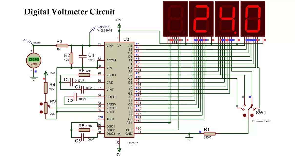
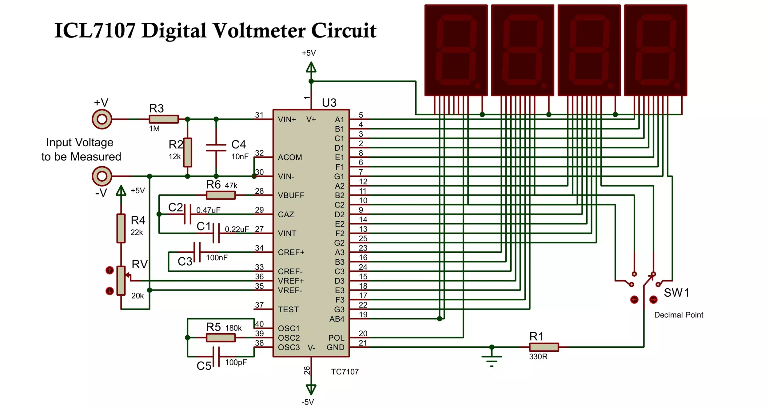
ICL7107 Digital Voltmeter Circuit Diagram
The core of this digital voltmeter is the ICL7107, which directly drives 4 common anode 7-segment LED displays without needing a separate microcontroller or display driver.
The voltmeter directly reads up to 99.9V DC, and with appropriate voltage divider scaling, it measures up to 2kV DC or more.
Construction of Voltage Meter
The construction involves placing the ICL7107 IC centrally on a PCB or breadboard, followed by:
- Wiring the Display: The ICL7107 pins are connected to the corresponding segments of the 7-segment displays. Pins 2 to 8 for 1st segment, pins 9 to 25 are for 2nd, 3rd and 4th segment with negative sign.
- Voltage Divider Setup: The input voltage is scaled using a voltage divider network.
- Capacitor Placement: Capacitors at pins 27 (integrator), 29 (auto-zero), 33 & 34 (reference), and oscillator pins 38, 39, 40.
- Reference Voltage: A 22kΩ resistor and 20kΩ potentiometer set the reference voltage required for scaling.
- Power Supply: A regulated 5V supply is provided using LM7805 and LM7905. (A 1N4007 diode can protect against polarity reversal).
Working of Digital Voltmeter Circuit
The ICL7107 based digital voltage meter circuit converts the analog input voltage into a digital signal and displays it directly on a 7-segment display.
Step-by-step Working:
- Input Voltage Handling:
- The voltage divider circuit (R2 and R3) reduces the input voltage to bring it within the acceptable input range of the ICL7107 (200 mV, 2 V, or 20 V).
- Analog to Digital Conversion:
- The IC compares the input signal with its internal reference voltage (set via the Resistor + potentiometer setup).
- It integrates the voltage over time, using precision capacitors and resistors.
- Display Driver:
- The digital output is decoded into 7-segment format internally by the IC.
- The segments are directly driven by the ICL7107 pins, making it very simple to wire.
- Auto-Zeroing & Calibration:
- Auto-zero functionality continuously removes offset errors.
- The potentiometer helps calibrate the full-scale voltage and improve accuracy.
- AC Measurement (Optional):
- For AC voltages, use a precision full-wave rectifier circuit followed by a filter capacitor to convert AC to DC.
- The output is then scaled and sent to the ICL7107 input.
Voltage Ranges
| Voltage Range | R2 Value (Voltage Divider) |
|---|---|
| 0 – 20V | 1.2kΩ |
| 0 – 200V | 12kΩ |
| 0 – 2kV | 120kΩ |
Use high-voltage rated resistors for voltage dividers in high-voltage applications.
Design Tips and Considerations
- Integrator Resistor (Pin 28): Use 47kΩ for 200mV range or 470kΩ for 2V full scale.
- Integrator Capacitor (Pin 27): 0.22μF polypropylene recommended.
- Auto-Zero Capacitor (Pin 29): 0.47μF for low noise, or 0.047μF for faster recovery.
- Reference Capacitors (Pin 33, 34): Use 1μF to minimize roll-over error, especially with large common-mode voltages.
- Oscillator: Set the oscillator using a 180kΩ resistor and 100pF capacitor, using the formula: f = 0.45/RC = 25kHz
- Display Flicker: Use filtering capacitors close to the IC and display lines to reduce flicker.
Advantages
- No Microcontroller Needed: Simplifies design and reduces cost
- Integrated Display Driver: Drives LED display directly
- High Accuracy: Auto-zeroing and differential input improve measurement stability
- Scalable Voltage Measurement: With external divider network
- Portable: Can be powered with batteries
- Low Component Count: Easy to assemble and maintain
Disadvantages
- Limited to LED Displays: ICL7107 cannot drive LCDs (use ICL7106 for that)
- No Serial Output: Cannot interface easily with digital systems for data logging
- Limited Voltage Range: Requires external scaling and protection for high voltages
- Sensitive to Noise: Must be carefully filtered and shielded, especially for low-voltage readings
- AC Measurement Needs External Circuit: Only reads DC natively
Applications
- Multimeters
- Panel Voltmeters and Ammeter for Power Supplies
- Battery Voltage Monitors
- Solar Charge Controllers
- Industrial Instrumentation Panels
- Educational Projects
- DIY Electronics Kits
Conclusion
The ICL7107-based digital voltmeter is a compact, reliable, and cost-effective solution for measuring voltages in the range of millivolts to kilovolts (with dividers). Thanks to its built-in ADC and LED driver, it simplifies digital voltmeter construction without the need for microcontrollers or complex programming.
With the right voltage divider and filtering techniques, you can build both AC and DC voltmeters suitable for lab, industrial, or field applications. Its simplicity, combined with high precision and versatility, makes it one of the most practical ICs for digital voltage measurement projects.
TDA2030 Audio Amplifier Circuit: Mono, Stereo and Bass Amplifier
Linear Regulated Power Supply Block Diagram & Circuit Diagram

Good