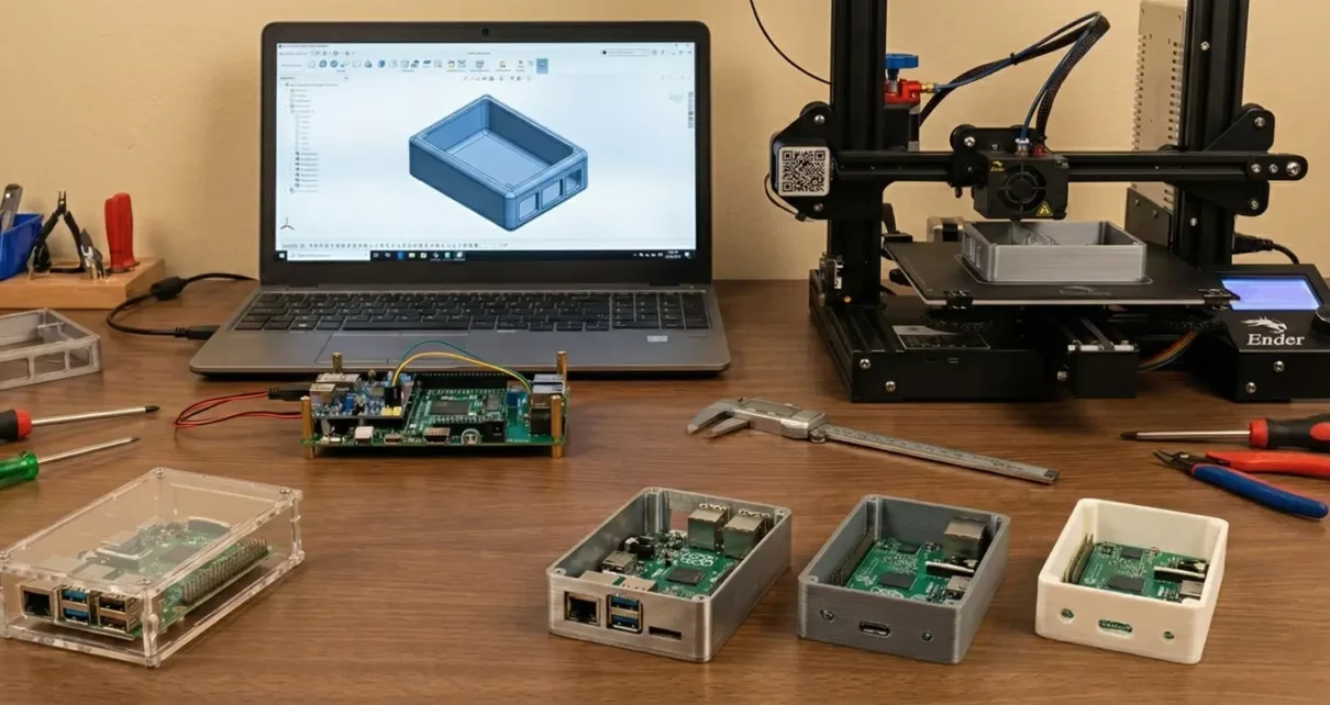
Every electronics project reaches a point where the circuit works, the code runs, and the breadboard prototype does what it is supposed to do. The next step is putting it into something that protects the board, manages heat, and looks like an actual product rather than a tangle of wires zip-tied to a plastic box.
Enclosure design is where electronics engineering meets mechanical engineering, and most electronics-focused makers and engineers have less experience on the mechanical side. The result is usually one of two outcomes. Either the project stays as an exposed PCB forever, or it ends up in a generic off-the-shelf box that does not quite fit and requires awkward modifications to accommodate connectors, displays, and ventilation.
A custom enclosure solves both problems, but designing one well requires thinking about materials, thermal management, manufacturing constraints, and assembly from the beginning rather than treating the enclosure as an afterthought.
Choosing the Right Material
How Material Selection Impacts Performance
The material you choose for your enclosure affects thermal performance, weight, EMI shielding, durability, and manufacturing cost. There is no single best material. The right choice depends on what your circuit does and where it will be used.
Aluminum for Heat Dissipation and EMI Shielding
Aluminum is the most common choice for electronics enclosures that need heat dissipation or EMI shielding. It conducts heat well, provides a natural Faraday cage when fully enclosed, is lightweight, and machines easily. For projects involving high-speed PCB designs where EMI shielding and signal integrity matter, aluminum is often the only practical option. 6061-T6 is the most widely available alloy for machined enclosures. It offers good strength, corrosion resistance, and a clean surface finish after anodizing.
Steel for Strength and Magnetic Shielding
Steel works for enclosures that need higher structural strength or better magnetic shielding. It is heavier and harder to machine than aluminum, but for industrial control boxes or high-power applications where rigidity matters more than weight, steel is a reasonable choice. Stainless steel offers corrosion resistance in outdoor or washdown environments, but it is more expensive and harder to machine.
Plastic Options: ABS and Polycarbonate
ABS and polycarbonate are the standard choices for plastic enclosures. ABS is inexpensive, easy to machine or 3D print, and works well for low-power consumer electronics where EMI shielding is not a concern. Polycarbonate offers better impact resistance and can handle higher temperatures. Neither material provides EMI shielding on its own, but conductive coatings or internal shielding can be added if needed.
CNC Machining for Low-Volume Production
For projects that need to be sourced in small quantities, CNC machining platforms make it practical to have custom aluminum or steel enclosures manufactured without the tooling investment required by injection molding. This matters for electronics projects where you might only need 10 to 200 units, and the economics of plastic injection molding do not make sense.
Designing for Thermal Management
Why Heat Control Matters in Electronics
Heat is the enemy of electronic reliability. Every degree of temperature rise above a component’s optimal operating range reduces its lifespan, and enclosures that trap heat without providing a dissipation path will eventually cause failures.
Calculating Total Power Dissipation
The first step in thermal design is knowing how much heat your circuit generates. Add up the power dissipation of every major component, including voltage regulators, power transistors, MOSFETs, and motor drivers. That total wattage needs to go somewhere, and the enclosure is your primary tool for managing it.
Passive Convection for Low-Power Projects
For low-power projects generating less than a watt or two, passive convection through the enclosure walls is usually enough. Adding ventilation slots or holes on the top and bottom of the enclosure creates a chimney effect where warm air rises out and cooler air enters from below. Keep vent openings on opposite sides or on the top and bottom rather than on the same face so that air actually flows through the enclosure rather than circulating in a dead zone.
Using the Enclosure as a Heat Sink
In higher-power circuits, the enclosure itself can serve as a heat sink. Mounting power components directly to an aluminum enclosure wall with thermal pads or thermal paste allows heat to conduct through the metal and dissipate from the outer surface. This approach works well for linear voltage regulators, power MOSFETs, and LED drivers. The key is to ensure good thermal contact between the component and the enclosure wall, which means the mounting surface needs to be flat and smooth.
Adding External Heat Sink Fins
When passive cooling is insufficient, you can add heat sink fins to the enclosure’s exterior. Machined aluminum enclosures can incorporate fins directly into the design, eliminating the need for separate heat sink components. The fin height, spacing, and orientation all affect performance. Fins should be oriented vertically when the enclosure is in its normal operating position so that convection currents flow naturally along the fin surfaces.
When to Use Forced Air Cooling
Forced air cooling with fans is the last resort. It works, but fans add noise, require additional power, create openings for dust and moisture, and eventually fail. If your thermal analysis shows that you need a fan, it is worth revisiting the circuit design to see if power dissipation can be reduced before committing to active cooling.
Accounting for Connectors, Displays, and User Interfaces
External Component Layout and Enclosure Geometry
The layout of external-facing components drives most of the enclosure’s geometry. USB ports, power connectors, antenna SMA jacks, LED indicators, buttons, display windows, and ventilation openings all need cutouts in the enclosure walls, and each one has specific dimensional and positional requirements.
Planning Connector Placement on the PCB
Start by defining the connector layout on your PCB before designing the enclosure. Following solid PCB design rules and guidelines early in the process makes the mechanical side much easier to manage. Placing all connectors on one or two faces of the board significantly simplifies the enclosure design. A board with connectors on all four edges requires cutouts on every enclosure wall, which increases machining time and makes assembly more difficult.
Ensuring Proper Clearance for Mating Connectors
For each connector, check the mating connector’s dimensions and add clearance for the plug or cable. A USB-C port on the PCB might only be 9mm wide, but the mating plug housing is wider, and your enclosure cutout needs to accommodate the plug with enough clearance for the user to insert and remove it without fighting the case. The same applies to barrel jacks, DB-9 connectors, Ethernet jacks, and any other interface where an external plug enters the enclosure.
Designing Accurate Display Openings
Display windows require special attention. If your project uses an LCD or OLED display, the enclosure needs an opening that exposes the active display area without covering pixels at the edges. For touch displays, the enclosure opening needs to be large enough for the touch-sensitive area, not just the visible area. Acrylic or polycarbonate windows can be bonded over display openings to protect the screen while maintaining visibility.
Button and Switch Cutout Considerations
Buttons and switches need cutouts that allow the actuator to protrude through the enclosure wall with minimal wobble. If you are using tactile switches mounted on the PCB, the enclosure wall thickness and the switch plunger height need to be compatible so that pressing the enclosure-mounted button cap actually actuates the switch underneath.
IP Ratings and Environmental Protection
If your electronics project will be used outdoors, in a factory, or anywhere that exposes it to dust, water, or chemical splash, you need to design the enclosure for a specific IP (Ingress Protection) rating.
IP ratings use two digits. The first digit indicates protection against solid particles (dust), and the second indicates protection against water. An IP65-rated enclosure is completely dust-tight (6) and protected against water jets from any direction (5). An IP67 rating adds protection against temporary submersion.
Achieving a meaningful IP rating requires gaskets or O-rings at every seam where the enclosure halves meet, sealed cable glands for every wire or cable that enters the enclosure, and sealed or membrane-covered switches and indicators. The enclosure design needs to include a groove for the gasket that provides consistent compression when the two halves are fastened together.
For machined aluminum enclosures, the gasket groove is typically cut into one half of the enclosure with a width and depth matched to the gasket cross-section. Silicone gaskets are the most common choice because they remain flexible over a wide temperature range and resist UV degradation.
Cable entry points are often the weakest link in an otherwise well-sealed enclosure. PG or metric cable glands with rubber compression seals provide reliable sealing for round cables. For flat cables or PCB-mounted connectors that need to be accessible from outside, sealed connector housings with integrated O-rings are available from manufacturers like Amphenol and TE Connectivity.
PCB Mounting and Internal Layout
How the PCB sits inside the enclosure affects assembly, serviceability, vibration resistance, and thermal performance. The two most common approaches are standoff mounting and rail mounting.
Standoff Mounting Method
Standoff mounting uses threaded brass or aluminum standoffs that screw into the enclosure base and hold the PCB at a fixed height above the bottom surface. This leaves an air gap beneath the board for airflow and prevents the solder joints on the bottom of the PCB from contacting the enclosure. Standard M3 standoffs are the most common size for electronics enclosures, and your PCB should include mounting holes sized for M3 screws at the corners and at any point where a heavy component might cause the board to flex.
Rail Mounting Method
Rail mounting uses internal grooves or channels machined into the enclosure walls that allow the PCB to slide in from one end. This approach is common in industrial enclosures and makes board replacement easier since the enclosure does not need to be fully disassembled. The tradeoff is that the PCB edges must be free of components where they contact the rails, and the board thickness must match the rail slot width.
Ensuring Proper Vertical Clearance
Leave enough clearance between the tallest component on the PCB and the enclosure lid. Electrolytic capacitors, transformers, heat sinks, and tall connectors all need headroom. Understanding the PCB manufacturing and assembly process helps here, since component heights vary depending on whether parts are surface-mount or through-hole. A good practice is to export the PCB assembly as a 3D model and import it into your enclosure CAD file so you can visually verify that nothing interferes with the lid or walls.
Managing Internal Wiring
Keep internal wiring organized and secured. Loose wires inside an enclosure can block airflow, vibrate against sharp edges, and create intermittent connections over time. Cable ties, adhesive cable mounts, and short wires runs between the PCB and panel-mounted connectors all help keep the interior clean.
Designing for Manufacturability
How CAD Decisions Impact Cost and Lead Time
The decisions you make in CAD directly affect the cost to manufacture your enclosure and how long it takes to arrive. A few simple design rules can significantly reduce both cost and lead time.
Maintaining Uniform Wall Thickness
Maintain uniform wall thickness wherever possible. Sudden changes in wall thickness cause warping in machined parts and create stress concentrations. For aluminum enclosures, 2mm to 3mm wall thickness is standard for handheld or benchtop devices. For larger industrial enclosures, 3mm to 5mm provides better rigidity.
Using Standard Internal Corner Radii
Use standard radii on internal corners. A CNC end mill cannot produce a perfectly sharp internal corner, so every inside corner will have a radius equal to at least the radius of the cutting tool. Designing your corners with a 1mm to 2mm radius from the start avoids the need for EDM finishing or secondary operations that add cost.
Avoiding Deep and Narrow Pockets
Avoid deep, narrow pockets that are difficult to machine. If a pocket is more than four times as deep as its narrowest dimension, it requires a long, thin cutting tool that deflects under load and produces a poor surface finish. Redesigning deep pockets as through-holes with a separate cover plate is usually cheaper and produces better results.
Reducing CNC Machine Setups
Minimize the number of setups required. Each time you remove a part from the CNC machine, reposition it, and re-clamp it, you add time and introduce positional error. Design the enclosure so that you can machine most features from two sides (top and bottom) to keep the cost down. When you place features on all six faces of a rectangular enclosure, you require multiple setups or a five-axis machine, both of which increase cost.
Adding Alignment Features Between Enclosure Halves
Add alignment features between the enclosure halves. Use dowel pin holes, tongue-and-groove joints, or locating bosses to ensure that the two halves register precisely every time you assemble them. Without alignment features, the halves may shift slightly each time you open and close the enclosure, eventually wearing the mounting holes and creating gaps.
Surface Finish and Appearance
The surface finish of your enclosure affects both appearance and function. For aluminum enclosures, the most common options are bead blasting, anodizing, and powder coating.
Bead blasting produces a uniform matte texture that hides minor machining marks and fingerprints. It is inexpensive and works well as a pre-treatment before anodizing.
Anodizing creates a hard, wear-resistant oxide layer on the aluminum surface that can be dyed in various colors. Type II anodizing is the standard for consumer electronics enclosures, producing a 10-25 µm coating that resists scratches and corrosion. Type III (hardcoat) anodizing produces a thicker, harder layer for industrial or military applications. Anodizing also provides a non-conductive surface, which can be beneficial or problematic depending on whether you need the enclosure to serve as an electrical ground.
Powder coating offers the widest range of colors and textures, but adds more thickness to the part than anodizing. This means that tight-tolerance features, such as connector cutouts and mating surfaces, need to account for coating thickness in the design. Powder coating also fills in fine details and sharp edges, so any engraved text or logos should be deep enough to remain legible after coating.
For plastic enclosures produced by 3D printing, vapor smoothing (for ABS) or light sanding followed by painting produces a finished look. For machined plastic parts, the as-machined surface is often acceptable without additional treatment.
Conclusion
A well-designed enclosure is not just a box that holds a PCB. It is a functional part of the electronics system that manages heat, provides EMI shielding, protects against environmental hazards, and presents a clean interface to the user. The best time to start designing it is while the PCB layout is still in progress, not after the board is finished and you discover that the connector placement makes the enclosure impossible to manufacture.
Model the enclosure in 3D alongside the PCB assembly, verify thermal performance with basic calculations before committing to a manufacturing method, and design for the manufacturing process you plan to use rather than designing in a vacuum and hoping someone can make it. The gap between a working prototype and a finished product is almost entirely mechanical, and the enclosure is the biggest piece of that puzzle.
Linear Regulated Power Supply Block Diagram & Circuit Diagram
High Speed PCB Design: Essential Wiring Techniques for Optimal Performance
