A Hall effect transducer is a sensor that detects a magnetic field and converts it into a proportional electrical signal using the Hall effect phenomenon. It is widely used for current sensing, position sensing, speed detection, proximity sensing, and magnetic field measurement in industrial, automotive, and consumer electronic systems.
Unlike conventional mechanical or contact-based sensors, Hall effect transducers operate without physical contact, providing high reliability, long life, and excellent performance even in harsh environments.
The Hall effect phenomenon was discovered by Edwin Herbert Hall in 1879, and since then it has become the foundation for a broad class of magnetic field sensing devices.
Hall Effect Principle
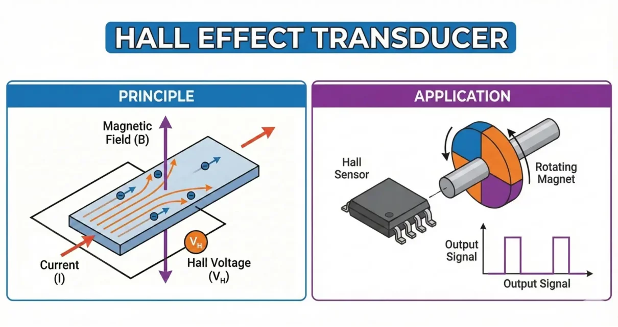
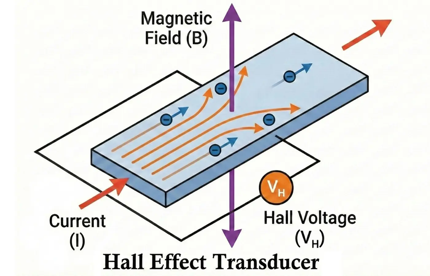
When a current-carrying conductor or semiconductor is placed in a magnetic field perpendicular to the direction of current flow, a transverse voltage develops across the material. This voltage is called the Hall voltage.
Mathematical Expression:
VH = B⋅I/n⋅q⋅t
Where:
- VH = Hall voltage
- B = Magnetic flux density
- I = Control current
- n = Charge carrier density
- q = Electron charge
- t = Thickness of the Hall element
This voltage is proportional to the magnetic field strength and can be amplified and conditioned to generate usable output signals.
Construction of Hall Effect Transducer
A Hall effect transducer consists of the following main parts:
- Hall Element
- A thin rectangular plate made from semiconductor materials such as Indium Arsenide (InAs), Gallium Arsenide (GaAs), or Silicon.
- It has four terminals: two for current input and two for Hall voltage output.
- Biasing Circuit
- Provides a constant current through the Hall element.
- Signal Conditioning Circuit
- Includes an amplifier, filter, and temperature compensation network.
- Converts the low-level Hall voltage (in microvolts) into a usable analog or digital signal.
- Magnetic Concentrator (Optional)
- Ferromagnetic core used to concentrate the magnetic flux onto the Hall element for improved sensitivity.
- Output Stage
- May provide analog output, digital switching output, or PWM output.
Working of Hall Effect Transducer
- A constant current flows through the Hall element.
- When no magnetic field is present, Hall voltage is zero or minimal.
- When a magnetic field is applied perpendicular to the current:
- Charge carriers are deflected by the Lorentz force.
- A voltage develops across the element.
- This Hall voltage is amplified and conditioned.
- The output voltage or digital signal represents the magnitude or presence of the magnetic field.
Thus, the transducer converts a magnetic input into an electrical output.
Types of Hall Effect Transducers
- Linear Hall Effect Sensors
- Output voltage varies linearly with magnetic field strength.
- Used for current sensing and position measurement.
- Digital (Switching) Hall Effect Sensors
- Provide ON/OFF output when field crosses a threshold.
- Used for proximity detection and speed sensing.
- Latching Hall Effect Sensors
- Output remains latched until opposite polarity field is applied.
- Used in BLDC motor commutation.
- Ratio-metric Hall Effect Sensors
- Output is proportional to supply voltage and field strength.
- Used in automotive throttle and pedal sensors.
- Current Hall Transducers
- Designed with magnetic cores to sense current in conductors without contact.
Advantages of Hall Effect Transducers
- Non-contact operation
- High reliability and long service life
- Fast response time
- Works in dusty, oily, and wet environments
- Electrically isolated current measurement
- Compact size
- Low maintenance
Disadvantages of Hall Effect Transducers
- Limited accuracy compared to fluxgate or shunt sensors
- Sensitive to temperature variations
- Offset drift over time
- Requires external amplification
- Sensitive to external magnetic interference
Applications of Hall Effect Transducers
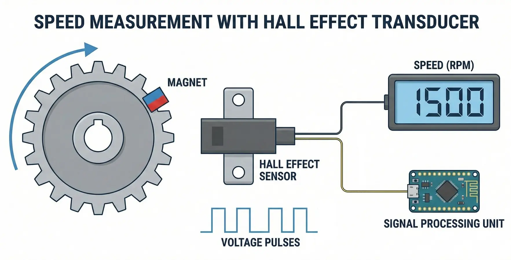
Speed Measurement
A rotating shaft is fitted with a ferromagnetic gear or toothed wheel. A Hall sensor is placed near the teeth. As each tooth passes the sensor, the magnetic field changes, producing a pulse.
Operation
- Each tooth → one voltage pulse
- Pulse frequency (f) is proportional to rotational speed.
N = 60 f/Z
Where:
- N = speed in rpm
- f = pulse frequency (Hz)
- Z = number of teeth
Advantages
- Non-contact measurement
- Works at low speeds
- Immune to dust and oil
Applications
- Automotive crankshaft speed sensing
- Motor speed control
- Conveyor belt monitoring
Displacement Measurement
A permanent magnet is attached to the moving object. A Hall sensor is fixed nearby. As the object moves, the distance between the magnet and sensor changes, causing a change in magnetic field and hence Hall voltage.
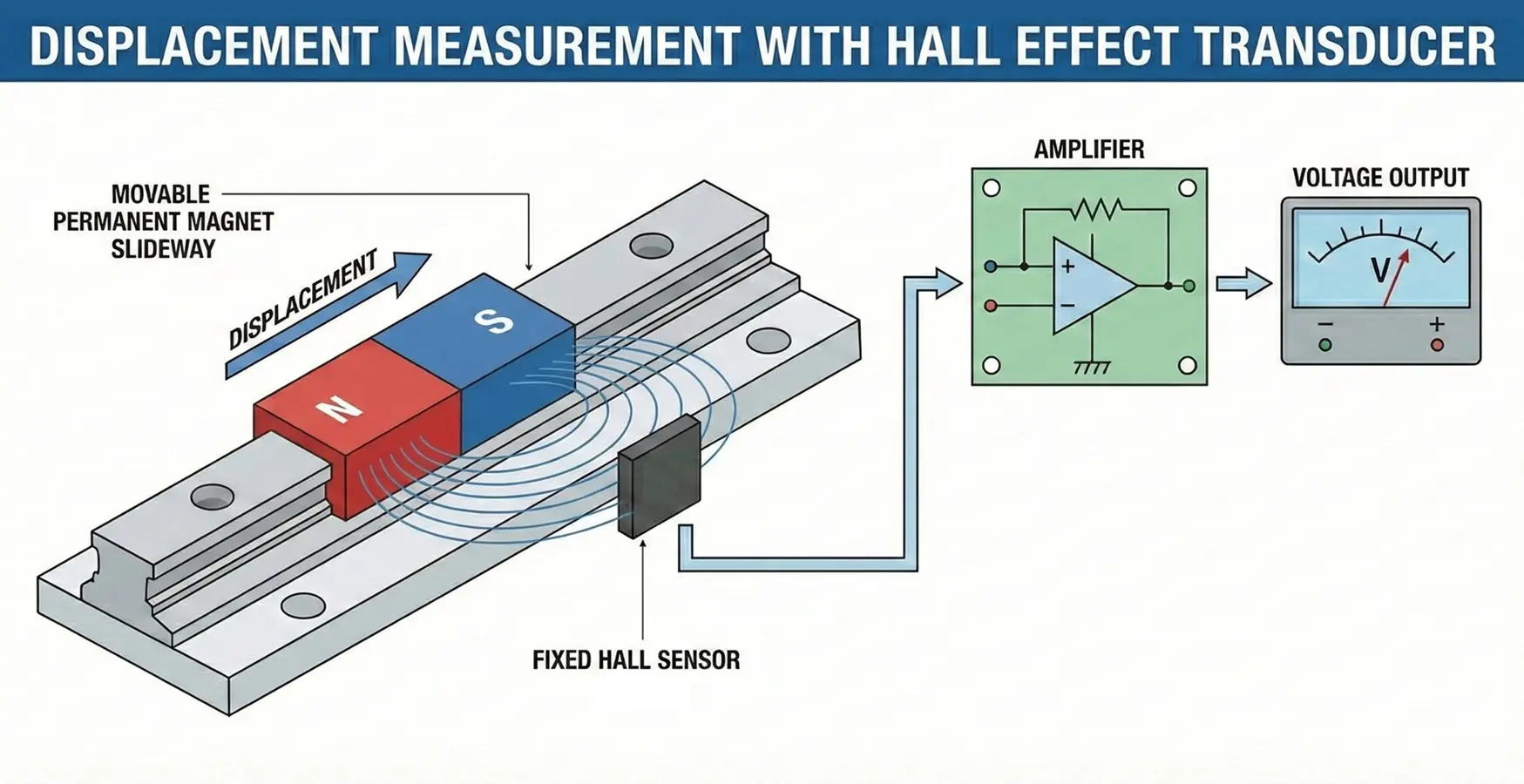
VH ∝ B(x)
Since B varies with displacement (x), the Hall voltage becomes a measure of displacement.
Characteristics
- Output is nonlinear over large distances
- Highly linear over small displacement ranges
- Can be calibrated for precise measurement
Advantages
- No mechanical contact
- High reliability
- Suitable for harsh environments
Applications
- Valve position sensing
- Throttle position sensors
- Linear actuators
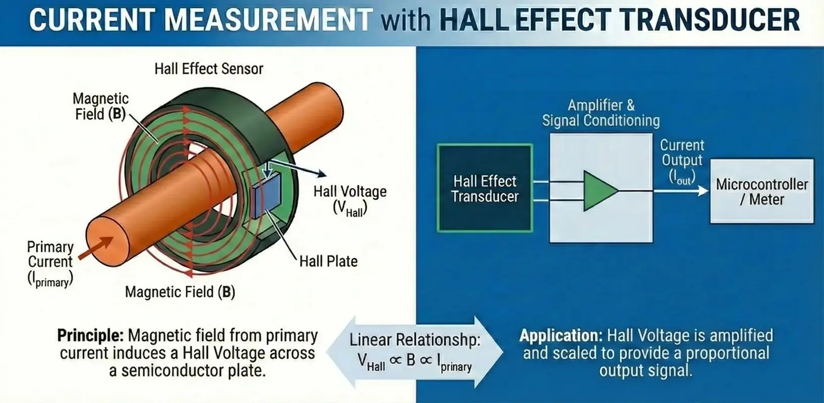
Current Measurement
The conductor carrying the current generates a magnetic field around it:
B = μ0I/2πr
A Hall sensor placed near the conductor measures this field, producing a voltage proportional to current.
Advantages
- Electrical isolation between sensor and conductor
- Can measure DC and AC currents
- No insertion loss
Applications
- Power electronics
- Battery management systems
- Inverters and UPS systems
Applications of Hall Sensor
Here are other useful applications of hall effect sensor as follow:
- Automotive
- Wheel speed sensors (ABS)
- Crankshaft and camshaft position sensors
- Throttle and pedal position sensing
- BLDC motor commutation
- Industrial
- Motor speed and direction sensing
- Conveyor position monitoring
- Proximity detection
- Current monitoring in drives and inverters
- Power Electronics
- SMPS current sensing
- Battery management systems
- Inverter and UPS current feedback
- Consumer Electronics
- Smartphones (lid open/close detection)
- Brushless DC fans
- Proximity detection
- Medical and Instrumentation
- Flow sensing
- Non-contact switches
- Magnetic field measurement instruments
Conclusion
Hall Effect Transducers play a vital role in modern electronic systems by providing accurate, reliable, and contactless measurement of magnetic fields, position, and current. Their simplicity, robustness, and versatility make them indispensable in automotive, industrial automation, and power electronics applications. Despite some limitations such as temperature sensitivity and offset drift, continuous advancements in semiconductor fabrication and signal conditioning techniques continue to enhance their performance and expand their application scope.
A1233, SS39ET/SS49E/SS59ET, ACS712, TMCS1100, ACS37610, A1250, and A1335 are some of the most popular and commonly used Hall-effect sensor ICs, supporting a wide variety of speed, position, and current-sensing applications.
What is a Sensor? Types of Sensors, Classification & Applications
IOT Based Air Quality Monitoring System with ESP32 & BME680 Sensor
