In this article, we will discuss Half Subtractor Circuit and Full Subtractor Circuit with their working principle, truth table, equations, Karnaugh maps (K-map) and applications.
Subtraction is a fundamental arithmetic operation in digital electronics, and logic circuits efficiently implement it. A subtractor is a combinational circuit that performs binary number subtraction in digital systems. These circuits play a crucial role in various arithmetic and logic operations in digital devices.
Binary Subtraction in Digital Electronics
Subtraction in digital electronics is performed using binary numbers. The two main methods used are:
- Direct Binary Subtraction
- Subtraction Using 2’s Complement
1. Direct Binary Subtraction
This method follows the same rules as decimal subtraction but in binary form.
Binary Subtraction Rules
- 0 – 0 = 0
- 1 – 0 = 1
- 1 – 1 = 0
- 0 – 1 = 1 (borrow 1 from the next higher bit)
Example of Direct Binary Subtraction
Subtract 0101 (5 in decimal) from 1010 (10 in decimal):
  1010   (Minuend)
- 0101   (Subtrahend)
------------
  0101   (Result = 5 in decimal)
No borrowing is needed in this case.
2. Subtraction Using 2’s Complement
Instead of direct subtraction, we use the 2’s complement of the subtrahend and add it to the minuend.
Steps to Perform Subtraction Using 2’s Complement:
- Find the 2’s complement of the subtrahend.
- Take the 1’s complement (invert all bits).
- Add 1 to the 1’s complement.
- Add the 2’s complement of the subtrahend to the minuend.
- If there is an extra carry, discard it. If not, the result is negative, and taking the 2’s complement of the result gives the magnitude.
Example of 2’s Complement Subtraction
Subtract 0101 (5 in decimal) from 1010 (10 in decimal):
- Find 2’s complement of 0101:
- 1’s complement of 0101 → 1010
- Add 1 → 1011 (2’s complement of 0101)
- Add 2’s complement of 0101 to 1010:
  1010
+ 1011
------------
  10101
Since we have a five-bit result, discard the leftmost carry bit, leaving 0101, which is 5 in decimal.
Example When Subtracting a Larger Number
Subtract 1010 (10 in decimal) from 0101 (5 in decimal):
- Find 2’s complement of 1010:
- 1’s complement of 1010 → 0101
- Add 1 → 0110
- Add 2’s complement of 1010 to 0101:
   0101
 + 0110
------------
   1011
The result is negative. To find the magnitude, take the 2’s complement of 1011:
- 1’s complement → 0100
- Add 1 → 0101 (5 in decimal)
Since the original subtraction was of a larger number from a smaller one, the final result is -5.
Let’s see the two types of Subtractor circuits in detail.
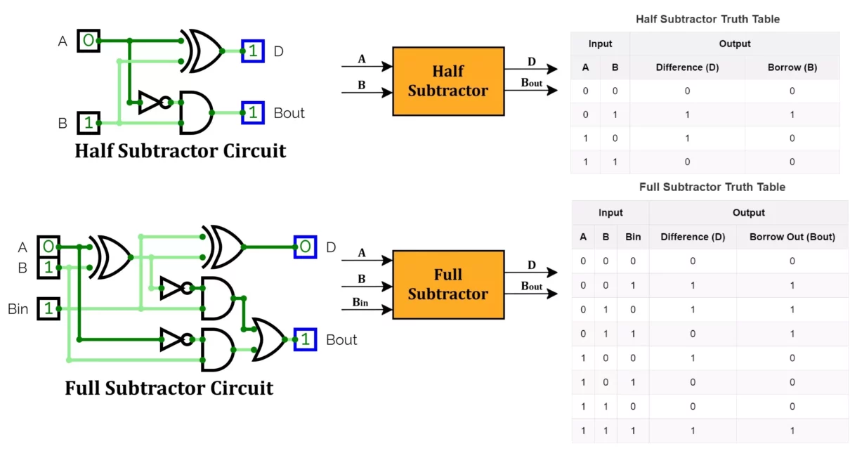
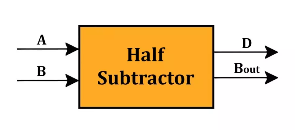
Half Subtractor Circuit
A half subtractor is a combinational logic circuit that subtracts two single-bit binary numbers, A and B. It provides two outputs:
- Difference (D)
- Borrow (B)
Logic Circuit Implementation
- The Difference (D) is obtained using an XOR gate.
- The Borrow (B) is obtained using a NOT and AND gate combination.
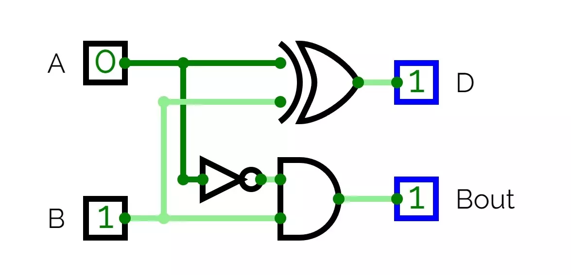
Circuit Diagram and Working
- Connect A and B to an XOR gate → Output is D.
- Pass A through a NOT gate, then AND it with B → Output is B.
Half Subtractor Truth Table
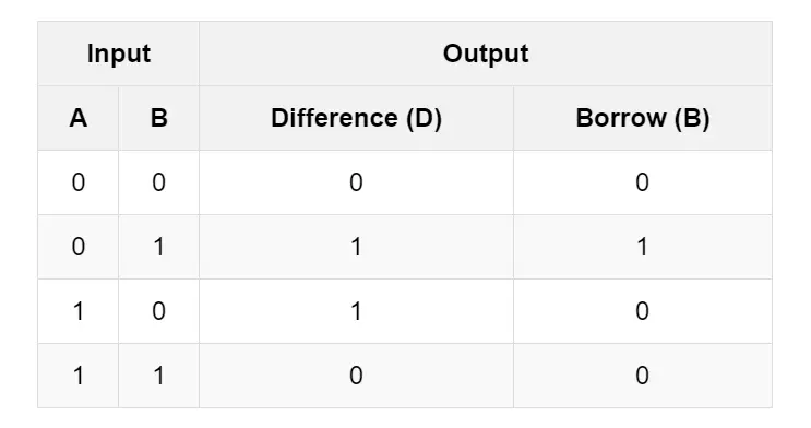
Equation for Half Subtractor
Difference Output:
The Difference output follows an XOR logic:
D = A ⊕ B
Borrow Output:
The Borrow output is generated when A is 0 and B is 1. This follows an AND-NOT logic:
B = A'B
Half Subtractor K Map
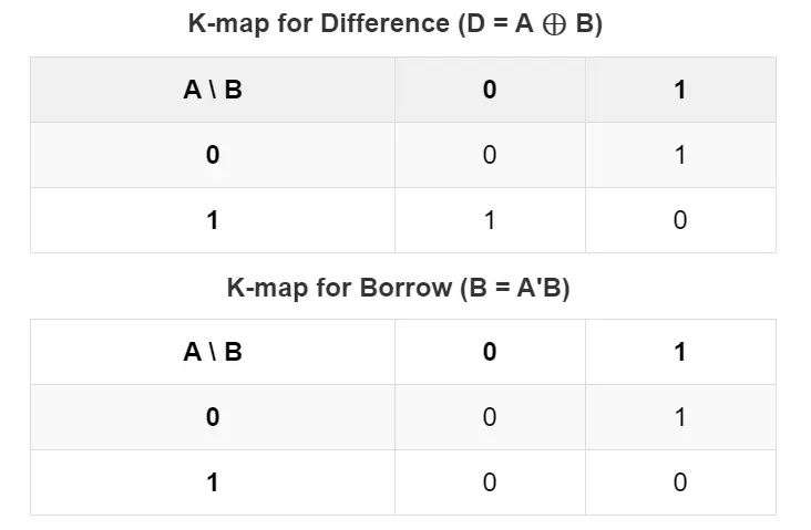
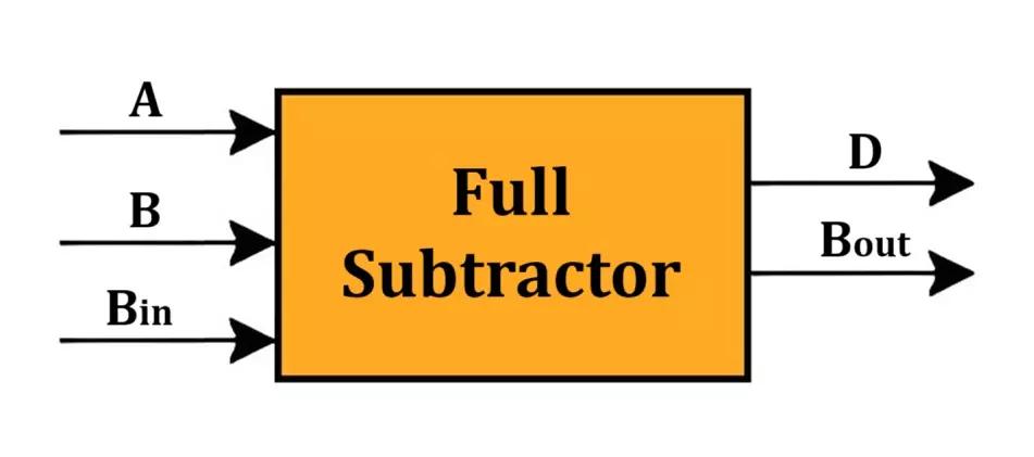
Full Subtractor Circuit
A full subtractor is a combinational circuit that performs subtraction on three bits: two input bits (A, B) and a borrow-in bit (Bin). It provides two outputs:
- Difference (D)
- Borrow Out (Bout)
Logic Circuit Implementation
- The Difference (D) is obtained using two XOR gates.
- The Borrow (Bout) is obtained using a combination of NOT, AND, and OR gates.
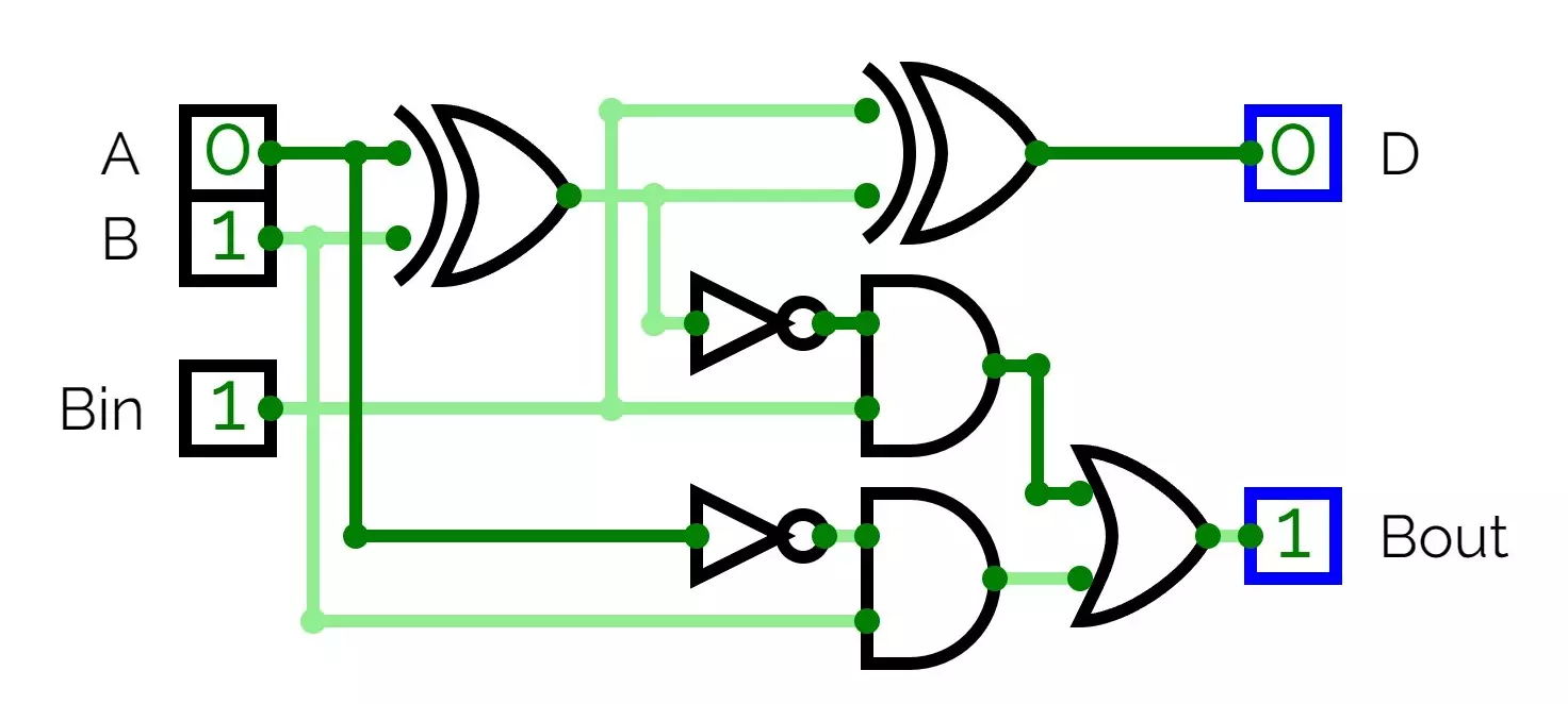
Circuit Diagram and Working
- Connect A and B to an XOR gate → Output is X (Intermediate XOR).
- Connect X and Bin to another XOR gate → Output is D (Final Difference).
- Pass A through a NOT gate, then AND it with B → Output is T1.
- Pass X through a NOT gate, then AND it with Bin → Output is T2.
- OR T1 and T2 → Output is Bout (Final Borrow).
Full Subtractor Truth Table
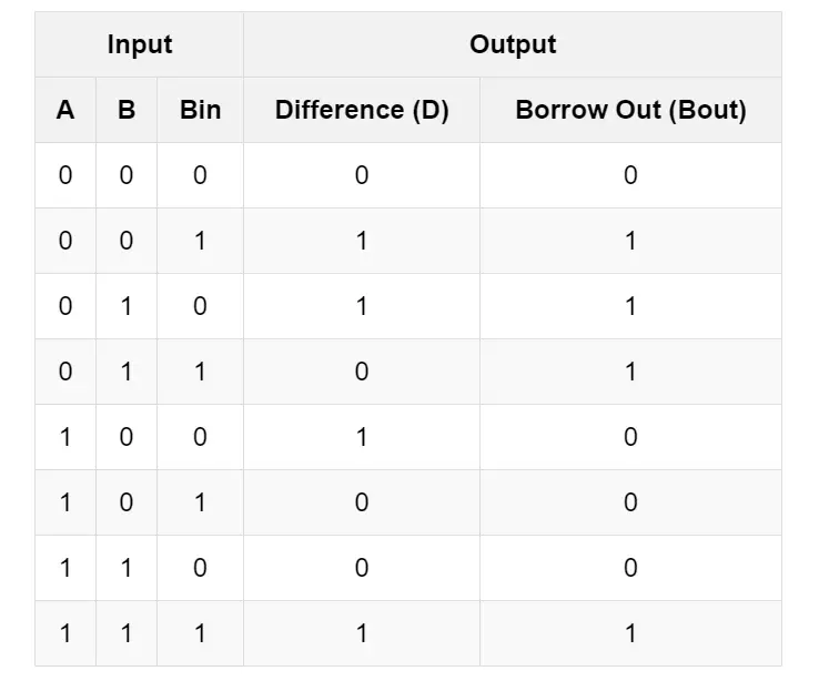
Equations for Full Subtractor
Difference Output:
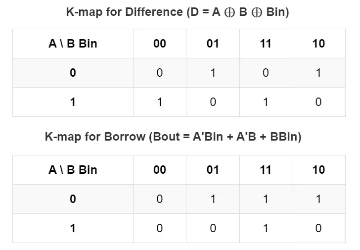
D = A ⊕ B ⊕ Bin
Borrow Out Output:
Bout = A'Bin + A'B + BBin
Full Subtractor K Map
Applications of Subtractors
- Digital Circuits – Used in microprocessors and arithmetic logic units (ALUs) for binary subtraction.
- Computers – Essential for performing arithmetic and logic operations.
- Calculators – Used in binary subtraction operations.
- Signal Processing – Used in digital signal processing (DSP) applications.
- Microcontrollers – Implemented in embedded systems for performing arithmetic computations.
Common ICs for Making Half and Full Subtractor Circuits
1. Basic Logic Gate ICs
You can build Half and Full Subtractors using basic logic gates:
- 7400 – Quad 2-input NAND gates
- 7402 – Quad 2-input NOR gates
- 7404 – Hex Inverter (NOT gates)
- 7408 – Quad 2-input AND gates
- 7432 – Quad 2-input OR gates
- 7486 – Quad 2-input XOR gates
2. Dedicated Subtractor ICs
Some ICs are designed specifically for arithmetic operations, including subtraction:
- 7483 – 4-bit Binary Full Adder (can be modified for subtraction using 2’s complement)
- 74283 – 4-bit Binary Adder/Subtractor
- 74LS85 – 4-bit Comparator (can be used in subtraction-based applications)
Conclusion
Subtractors are fundamental combinational circuits used in digital arithmetic. The half subtractor circuit handles simple binary subtraction of two bits, while the full subtractor circuit accounts for an additional borrow-in bit. Understanding their operation, equations, and K-maps is essential for designing efficient digital circuits. Adders and Subtractors are integral to modern computing and embedded systems, ensuring accurate and efficient binary computations.
Frequently Asked Questions (FAQs)
Q1: What is the main difference between a half subtractor and a full subtractor?
A half subtractor subtracts two bits, whereas a full subtractor subtracts three bits (including a borrow-in bit).
Q2: Why is a full subtractor more complex than a half subtractor?
A full subtractor considers the borrow-in bit, requiring additional logic gates for computation.
Q3: Can we design a full subtractor using two half subtractors?
Yes, two half subtractors and an OR gate can implement a full subtractor.
Q4: What logic gates are used to construct a subtractor?
A subtractor typically uses XOR, AND, OR, and NOT gates.
Q5: Where are subtractors used in real-life applications?
Digital computers, calculators, ALUs, and embedded systems widely use subtractors for arithmetic operations.
Half Adder and Full Adder Circuit, Truth Table, Equation with IC 7483
