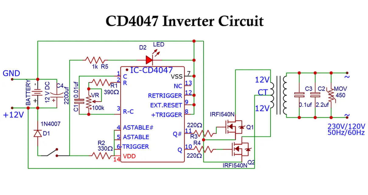
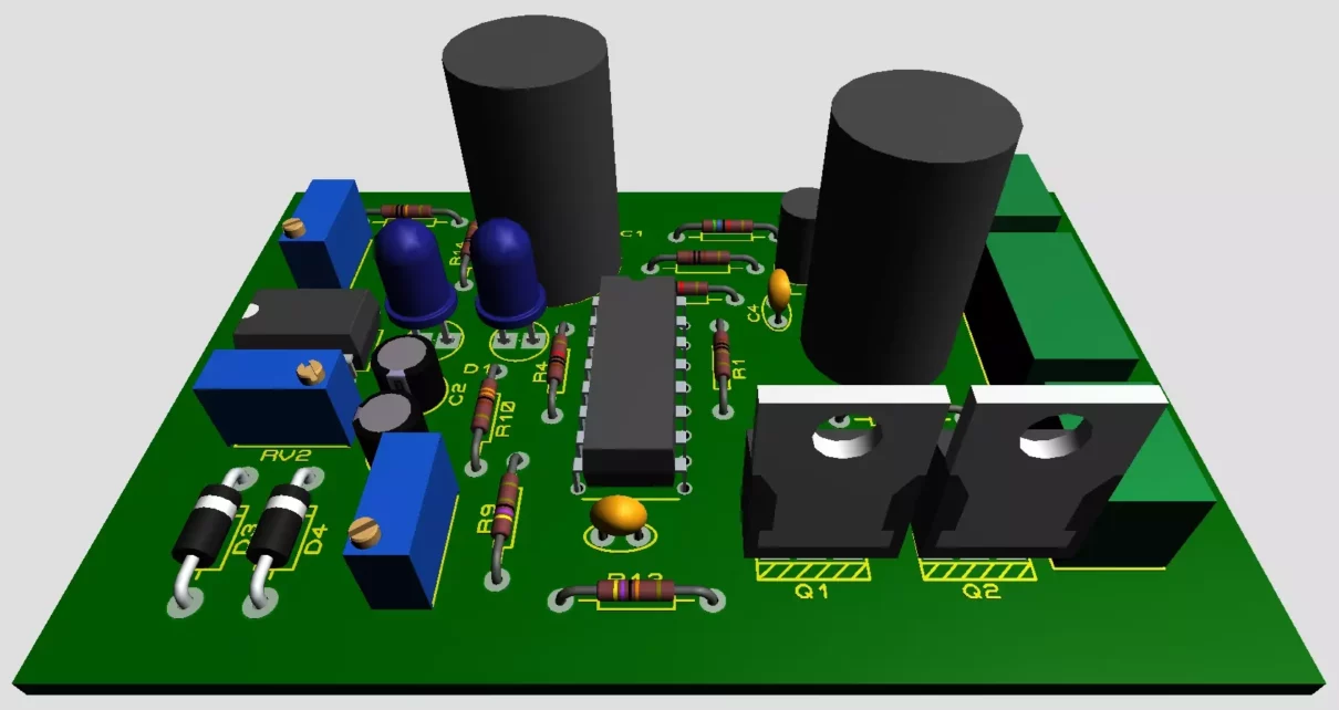
Here is a detailed explanation on types of variable speed drives, including their construction, working principles, advantages, disadvantages, and applications. Variable Speed Drives (VSDs), also known as Variable Frequency Drives (VFDs) or Adjustable Speed Drives (ASDs), are devices or systems used to control the speed and torque of motors by varying the frequency, voltage or […]
Inverters
H Bridge Inverter Circuit using IC SG3525 and MOSFET IRFZ44N
This article explains an H-Bridge inverter circuit based on the SG3525 IC and MOSFETs like IRFZ44N or IRF3205 or IGBT like GT50JR22, which can convert DC to AC with a frequency of 50Hz or 60Hz, suitable for most standard applications. The SG3525 is a widely used PWM (Pulse Width Modulation) controller IC designed for various […]
SPWM Inverter Block Diagram and Working
In this article, we’ll explore the SPWM inverter block diagram, its operation and break down the components in detail to understand the working. Inverter systems are critical in various applications, including renewable energy systems, solar power systems, electric motor drives, backup power supplies, and uninterruptible power supplies (UPS). A well-designed inverter system ensures seamless transition […]
SG3525 PWM Inverter Circuit Diagram and it’s Working
The SG3525 is a versatile PWM (Pulse Width Modulation) controller IC commonly present in inverter circuits to convert DC to AC at either 50Hz or 60Hz. Here’s a PWM based SG3525 inverter circuit with working. 1. Components Required: SG3525A PWM Controller IC N-channel MOSFETs (e.g., IRF3205) or IGBTs Transformers (Center-tapped, depending on the required output […]
VFD Variable Frequency Drive Working with Block Diagram
Let’s get started with Variable Frequency Drive working, also known as VFD. It is an electronic device that controls the speed of electric motors by adjusting the frequency of the electrical power supplied to them. These drives have become increasingly popular in recent years due to their energy-saving capabilities, improved process control, and reduced wear […]
12V to 230V Inverter Circuit Diagram using 555 timer IC
The circuit in this article shows you a simple way to build a 12v to 230v inverter circuit diagram of 100watt power using 555 IC. 555 is a timer ic which is used to generate time delay. On these properties, it can be used to make a power inverter. CD4047 Inverter circuit This Inverter does […]